Continue to Site

Eng-Tips is the largest engineering community on the Internet

Intelligent Work Forums for Engineering Professionals

  • Congratulations IDS on being selected by the Eng-Tips community for having the most helpful posts in the forums last week. Way to Go!

Substation structure base plates

Status
Not open for further replies.

structural-eng

Structural
Jan 26, 2017
39
I have a couple questions about designing base plates for substation structures. Can the base plate design method shown in ASCE 113 be used if column is an HSS and the base plate is open within the column for venting and drainage? I typically detailed 4" diameter holes for venting and drainage when using HSS8x8 column which meets the galvanizing associations minimum opening requirements but the fabricators constantly want larger openings. I know that the larger openings help improve drainage and require less tipping of the members but they also cut down the structural capacity of the base plate. I typically like to ensure that the base plates work by plate bending or a combination of torsion and plate bending and the large slots that the fabricators like to use don't allow me to look at the base plate bending the way I would like to.

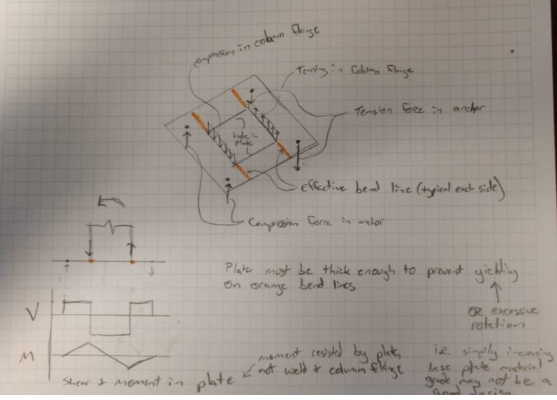
I have seen other threads on here that talk about detailing the column to extend into the base plate and then fillet welding the base plate to the column on the top and bottom. It seems that doing this creates a "flange plate" more so than a base plate and that you would need to be able to develop fixity in the welded connection between the plate and the HSS column with this condition but maybe I'm missing something.

We have detailed the weld between the column and the base plate as a full penetration weld in the past and are getting requests to find a way to make a single pass fillet weld work instead because of the large about of labor required for full penetration welds. I've seen some other threads on here where there was talk about full penetration welds but it wasn't clear if that was only for transmission structures (per ASCE 48-11) or if there are others that are using them for substations as well.
 
Replies continue below

Recommended for you

Have you looked into Daniel Horn's document on baseplates? Not sure if that helps, but he does address baseplates with large hole openings.

With the 4" hole on an HSS 8x8, your hole will be within the tube, the baseplate design is straight forward.
With the enlarged hole, just develop the strength of the plate/member with the weld. The plate would have a nearly identical "rigid" connection at the tube and the design would be pretty much the same. Just more thought to the weld design and the tube wall thickness selection.

Is there torsion on the section? Are you providing stiffeners or a thick-plate to address this?
Is the moment on the plate? Your anchor bolt layout will also dictate your yield line development.
 
You are correct, for a 4" hole within the HSS8x8 tube the base plate design is pretty straight forward. My question was more so when the hole is the entire inside of the tube.

I do have the Daniel Horn document and have reviewed it in the past. I'm just having a hard time getting comfortable with what type of welded connection between the column and the base plate is required in order to use the bend line approaches in ASCE 113 and the Horn document. The bend line approach uses an effective plate width that is no the same and the length of weld between the column and the base plate which seems odd. I have seen other threads on here that say when your base plate is entirely open below the column you should use an effective plate width that is the actual width of the plate minus the width of the column so you are essentially using the plate that is beyond the edge of the column to resist the bending but the bending is ultimately resisted by the weld which is located along a part of the plate that is being neglected.

The Horn document shows an example of the welded connection between the column and the base plate on page 107 where there is a large fillet weld on the top of the plate that resists 75-100% of the load and a smaller fillet weld on the bottom of the column-edge of the base plate hole that resists 25% of the load. I have seen this connection detailed numerous times but I haven't been able to find anything that explains how it actually works. I can size a fillet weld to transfer the overturning moment in the column to the base plate but that essentially coverts the load into a tension/compression load applied to the base plate and doesn't account for any bending at the welded joint which is how the bend line theory seems to be working. The bend line theory takes the bolt force and cantilevers it back to the column wall and I don't see how a fillet weld can develop the cantilever moment.

To answer your other questions -
There may be torsion a the base of the columns in some conditions but not typically and if there is torsion it is quite small.

We are open to including stiffeners but are starting by exploring what it takes to omit them as plenty seem to do their connections without them.

Yes, there is moment on the plate. The moment is on the order of 40-55 k-ft (ultimate).

The anchor bolts are (4) 1-1/4" diameter bolts on a 13"x13" square patterns.

Any additional insight would be appreciated.
 
structural-eng said:
I can size a fillet weld to transfer the overturning moment in the column to the base plate but that essentially coverts the load into a tension/compression load applied to the base plate and doesn't account for any bending at the welded joint which is how the bend line theory seems to be working. The bend line theory takes the bolt force and cantilevers it back to the column wall and I don't see how a fillet weld can develop the cantilever moment.

I don't believe that is quite the intent of the bend line theory. The intent is to ensure that the plate is sufficiently rigid enough to prevent precisely this situation (bending at the welded joint). The plate must be able to resist the induced bending by the couple created between the column flange and the anchor (and carry it back to the neutral axis.

In a typical case with no hole in the base plate, the effective bend line is taken across the face of the column and extended to either edge. This length is often limited by the designer based on bolt spacing, plate thickness, edge distance, etc (increasing a base plate from 16"x"16" to 24"x24" without increasing bolt pattern and/or thickness isn't a good justification to use a 24" long bend line as opposed to a 16" (or even smaller) bend line).

In the case you are describing, the effective length of the bend line is essentially limited to the width of the base plate minus the size of the hole (so if you have a 16" square base plate with a 7" square hole you have an effective bend line length of 4.5" on either side of the hole). The bend line theory then has you determine the moment in the plate at this bend line by multiplying the anchor load(s) by the (perpendicular) distance between the anchor(s) and the bend line. Using this moment you select a plate thickness that will limit the stress in the plate to an acceptable level and allow you to use the original assumption that the plate is rigid and therefore the weld does not need to (won't) carry any moment.

See quick (messy) sketch below of how I see the design intent of the bend line theory with a large hole in the base plate:
Base_Plate_Bending_tjsbbc.jpg
 
I appreciate your response dauwerda. You explanation is very helpful. Are you aware of any testing/reports that are available to back up your understanding? For liability reasons I really need something published that I can reference.
 
I am not, unfortunately. The closest thing I can come to is the utilization of this connection in practice. AASHTO's "standard spec for structural support for highway sign luminaires and traffic signals" makes reference to this connection with round and multi-sided poles, but it does not get into the design. Horn's document also addresses the large holes in base plates, but again it is more focused on round and multi-sided poles.

The end of this previous thread describes the same understanding that I have outlined above:

The AISC HSS Connections Manual also presents a method on pages 7-9 and 7-10 that is similar to this (below) method from the steel tube institute (these do not specifically address the large hole, but the bend line is no longer on the face of the column.
 
Status
Not open for further replies.

Part and Inventory Search

Sponsor