Eng-Tips is the largest engineering community on the Internet

Intelligent Work Forums for Engineering Professionals

Substation Voltage Regulator 4

Status
Not open for further replies.

BillyBob2021

Electrical
Sep 28, 2021
7
0
0
US
Hello,

I’m working at a distribution substation that has two feeders, each feeder has three voltage regulators (single phase regulators). I’ve been keeping track of how many times each month these regulators operate and an overall yearly sum per phase.

Ive noticed that one feeder we will call it 9L2 operates pretty equally across each phase per month and so far the overall yearly total per phase is around 12,000 - 13,000 operations.

For feeder 9L1 I’ve noticed C phase operates a lot more frequently than B and A phases anywhere between 8000- 14000 times per month and has already reached close to 80,000 operations tor this year. Whereas A and B phases operate less and have a total of around 40,000 operations for the year each. What could cause the C phase to operate so much. I’ve checked the bandcenter, bandwidth, and time delay and the settings are all the same across ABC phases for feeder 9L1.

Settings 9L1= bandcenter 122v
Bandwidth 1.5v
Time delay 55 sec

Settings 9L2= bandcenter 122v
Bandwidth 1.5v
Time delay 90sec

Im guessing that the 9L2 changes less frequently due to the time delay setting. But I’m
Trying to figure out why the 9L1 C phase changes tap positions far more frequently than A and B.

Thanks
 
Replies continue below

Recommended for you

Are the feeders equally transposed? Are there single phase loads on the feeders?
Look for a large single phase load, cycling on C phase.

--------------------
Ohm's law
Not just a good idea;
It's the LAW!
 
A cycling single phase load seems highly likely.

Also possible is a problem with the regulator on C phase:
-If the regulator has analog controls, some of the components could have drifted.
-If the regulator has digital controls, there could be dozens of other settings that could impact how regulator operates.
-If this has line drop compensation, verify the settings are identical, and the CTs are unshorted.
-If this has high voltage runback or first customer protection, verify that the runback settings coordinate with the bandcenter/bandwidth settings.

Outside the scope of your specific question, I was shocked at the huge number of operations on both sets of regulators. Using a slightly larger bandwidth is likely to dramatically reduce the number of operations.

waross- Is transposition on distribution systems common? In my area, the distribution always has B phase as the middle phase on the crossarm. I have not seen transposition on 115 kV lines and even shorter 230 kV transmission lines do not seem to have transposition.
 
waross- Is transposition on distribution systems common?
Good point.
However I have seen transpositions on transmission line on voltages lower than 115 kV.
Lack of transpositions on the incoming transmission feeders may be an issue.
At a distribution sub, the regulators may be reacting to primary/transmission voltage shifts.
The bandwidth seems very low. That would be 1.25% on a 120/208 Volt circuit.
On a distribution circuit, it seems to be an affront to reality.
I could accept a case where on long transmission spans on the incoming feeders, the change in reactance due to wind gusts changing the phase spacing may cause regulator action.
Do the numbers: 1.5 Volts as a PU value of a 13.8/7.97 kV distribution circuit.

--------------------
Ohm's law
Not just a good idea;
It's the LAW!
 
I know about as much as you could write with a crayon on paper and cram into a thimble on distribution but I'd expect the bandwidth to be something around 50V. I'd change those settings to 15V and see how the operation changes. If you're unsure then just triple what they're set to now and watch what happens to the operation frequency.

Keith Cress
kcress -
 
At such low voltages, I presume it is a stepless variac type regulator, where 1% to bandwidth is normal since there is no switching. It is a brushed core wound transformer where the brushes move up and down without breaking contact with the turns and so no arcing.

I would check for loose connections in phase C.

Muthu
 
Is there an R & X component on that regulator that doesn't match the other 2 phases? In the past we would set R/X values per phase and not have them matching across the board. Perhaps controls were changed out and someone didn't match the settings?

We typically see 1-3k operations per year at 2V band and 15-30sec delays, however, the tap changers that feed area lumber mills do run about 10-12k operations per year. I'd lean towards characteristics of the feeder's connected load.

Edit: Has the regulator actually been operated and compare the counter pre/post operation? I do remember an instance where we had an issue with the counter switch contacts bouncing causing erratic count increases.
 
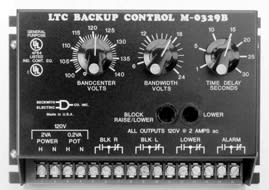
Unfortunately regulator controllers break all the usual rules EE's know about per unit calculations. Instead the controllers are always programmed in secondary units assuming a potential transformer with a 120 volt secondary. For more details on this kind of calculation see Beckwith-App-Note-17. Here is an faceplate from a regulator controller:
m-0329b_dtzyov.jpg


A voltage of 0.75 V on a 120 V basis corresponds with one tap position of 0.625% on a standard ANSI tap changer that has range of +/-10% and taps ranging from 16Raise to 16Lower. In order to avoid hunting, regulators require a bandwidth equal to at least 2 steps (1.25%), hence the minimum allowable bandwidth of 1.5V on a 120V basis.

Waross- I think it is unlikely conductor movement would account for significant changes in transmission voltages causing the OP's problem. Assuming an average 5% voltage drop on the transmission system, the line impedance would need to change by 25% to change the receiving end voltage by 1.25%. In a static case, achieving a 25% impedance would require huge amounts of differential conductor movement along the whole line. Although there is lots of conductor movement during a wind storm, I think much of the movement would cancel out when averaged across many spans of wire. However, going slight further off topic, I could be convinced that fault current flowing through a set of wires can cause enough simultaneous movement of wires to impact fault currents. In the case of a fault where the line impedance dominates the circuit, any change in line impedance would be directly proportional to changes in fault current.
 
If line drop compensation is used, unbalanced current could result in a different number of operations for different phases. Are the source side voltages balanced?
 
What does the nameplates tell you? If you have an inverted reg and the control is programmed for straight it will operate a bunch.
Quite honestly all those numbers sound extremely high anyway.
I get concerned if one of ours operate more than 7,000 times a year.

Picture of the name plates and the type of control would be helpful.
MJ-XL needs to go in the garbage.
SEL 2414 is a good control.
Cooper relays have some of the same features.

I have seen some where X&R is so high it bumps the upper limits and the regs fight themselves all day.
Forget the X&R and set it at 123 or 124.

2V bandwidth, 124 center, 20 second delay.
 
Status
Not open for further replies.
Back
Top