Continue to Site

Eng-Tips is the largest engineering community on the Internet

Intelligent Work Forums for Engineering Professionals

  • Congratulations MintJulep on being selected by the Eng-Tips community for having the most helpful posts in the forums last week. Way to Go!

Sudden reduction of Power Factor in a Motor feeder 1

Status
Not open for further replies.

charz

Electrical
Jan 11, 2011
95
In a 3 phase, particular motor feeder, the Power factor suddenly reduced from 0.98 to 0.82. The circuit is shown below,
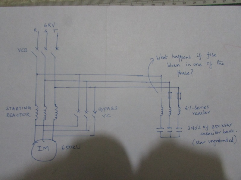
Blown_Fuse_Trouble_olgdtj.jpg


The company is not sending me to the plant, anyway I would like to know the cause of the trouble for my experience. I'm thinking of blowing of capacitor fuse in one phases. If so, what would be the Kvar output from the capacitor bank from the 2 capacitor banks.It means the two capacitor banks are in series with applied voltage of 6kV. Also the operator observed the noise from the 6% series reactor. What could have possibly went wrong?
 
Replies continue below

Recommended for you

No circuit shown charz.

Bill
--------------------
"Why not the best?"
Jimmy Carter
 
The kvar output will be half of the full amount. Output is proportional to the voltage squared = V²/X. X = 2·pi·f·C.

Voltage across each phase before the fuse blows is VLL/sqrt(3). Voltage after the fuse blows is VLL/2.

Output of each phase before the fuse blows is [VLL/sqrt(3)]²/X = VLL²·2·pi·f·C/3. Total of all three is VLL²·pi·f·C·2.

After the fuse blows, the output of each phase is [VLL/2]²/X = VLL²·2·pi·f·C/4. Output of two phases is VLL²·pi·f·C.
 
I can see it in the original Bill, must be you... [poke]

A blown fuse is a very likely suspect here. If I had to guess why, I'd say it was because of the primary reactor starting method and that the PFC caps are on line during starting. As PFC caps, the kVAR you select is for correcting the vars of the RUNNING motor. Starting current and the associated low PF causing stress to the PFC caps when started across-the-line (DOL) is not very significant because the duration is very short. When using a reduced voltage starting method, the amount of time the motor is pulling higher than normal current and lower than normal PF will result in the caps attempting to contribute more VARs into the circuit than they are rated to deliver for that extended time. They over heat and swell. You may not have actually blown the fuses if the caps have a "turkey timer" pop-out button indicating that their internal safety disconnect opened, but the effect is the same, the cap(s) is not available to the circuit.

On RV starting methods, I generally recommend having a PFC Cap Contactor ahead of the caps, isolating them until after the starting is done by controlling that cap contactor with, in your case, the reactor bypass contactor.


"You measure the size of the accomplishment by the obstacles you had to overcome to reach your goals" -- Booker T. Washington
 
jraef said:
When using a reduced voltage starting method, the amount of time the motor is pulling higher than normal current and lower than normal PF will result in the caps attempting to contribute more VARs into the circuit than they are rated to deliver for that extended time.
How can capacitors attempt to contribute more vars into the circuit? Capacitors are passive devices that contribute according to the voltage impressed on them. Q=V²/Xc
 
I calculated the improved PF due to the capacitor bank after getting the motor details. The corrected PF comes to Unity (attached). With the Unity PF, there could be a possibility of resonance. I haven't done any resonance analysis up to now. How to do the resonance analysis? The details which need are Motor inductance, Capacitance of capacitor, and does the source impedance (from plant transformer till the motor terminal) matter?
 
 http://files.engineering.com/getfile.aspx?folder=a35c8a50-972b-4dcb-834c-e602feef54ba&file=PF_calculation.xlsx
Maybe, the noise is coming from the motor, too? Having caps on just two of the phases would create negative sequence imbalance that might cause the motor to growl due to reverse torque.
 
If there is a negative sequence relay protection, can the feeder be able to detect this fault? If so, how should we calculate the percent of imbalance in case of single fuse blown in the capacitor?
 
I see it now.
I remember a wise old head electrician. Whenever he passed a bank of caps he would lightly drag his hand across the cans. If one can was cooler he would have someone check the fuses.

Bill
--------------------
"Why not the best?"
Jimmy Carter
 
I was told that after replacing one of the capacitor, the power factor improved to 0.98. The fuse did not blow.
What could be the cause for reduced capacity of a capacitor?
 
charz said:
I was told that after replacing one of the capacitor, the power factor improved to 0.98. The fuse did not blow. What could be the cause for reduced capacity of a capacitor?
An open circuit in the capacitor (wire burnt open before blowing the fuse).
 
It was not a case of open circuit. When they ran the motor with 2 capacitors, the PF was 0.76, but when they ran with three capacitors, the PF was 0.82 and after replacing the faulted capacitor, the PF again increased to 0.98.
 
charz said:
It was not a case of open circuit. When they ran the motor with 2 capacitors, the PF was 0.76, but when they ran with three capacitors, the PF was 0.82 and after replacing the faulted capacitor, the PF again increased to 0.98.
Multiple cans per phase with one can open circuited?
 
To expand on jghrist's post, internal fault, internal fuse. One of several sections.

Bill
--------------------
"Why not the best?"
Jimmy Carter
 
It may be a capacitor that worn off, reducing it capacitance. This way, the reactance power will not be same, not correcting the power factor with the same efficiency
 
HamburgerHelper said:
Maybe, the noise is coming from the motor, too? Having caps on just two of the phases would create negative sequence imbalance that might cause the motor to growl due to reverse torque.

Could you please elaborate? My understanding is that when the fuses of the capacitor bank blown, the Motor simply draws the required reactive vars from the utility on that particular phase. I understand that in case of the Main fuse on the way to motor terminal blowing, negative sequence current/voltage arises. But in this case,does the negative sequence currents or voltages exists because of blown fuse of the capacitor bank.
 
Status
Not open for further replies.

Part and Inventory Search

Sponsor