Eng-Tips is the largest engineering community on the Internet

Intelligent Work Forums for Engineering Professionals

  • Congratulations waross on being selected by the Tek-Tips community for having the most helpful posts in the forums last week. Way to Go!

Suggestions for H/L/LL level switches in a large tank? 1

Status
Not open for further replies.

amazing azza

Industrial
Apr 26, 2017
130
0
0
US
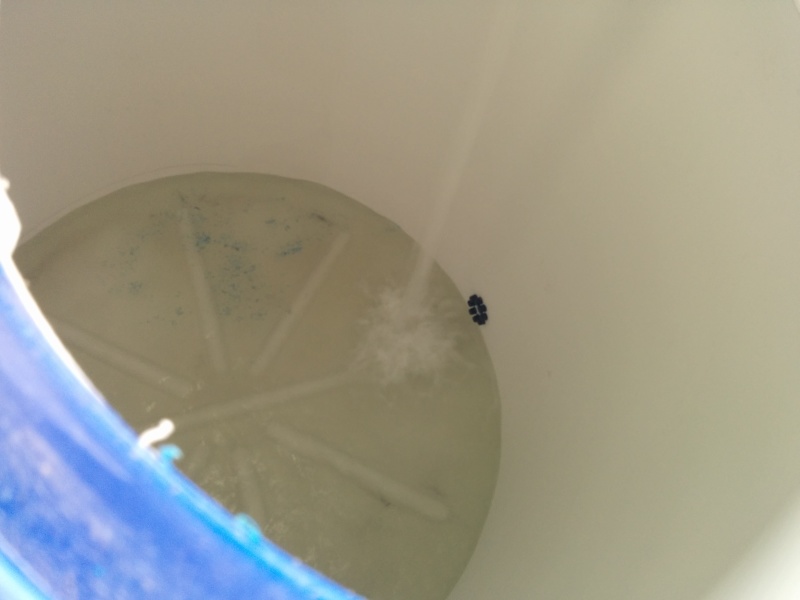
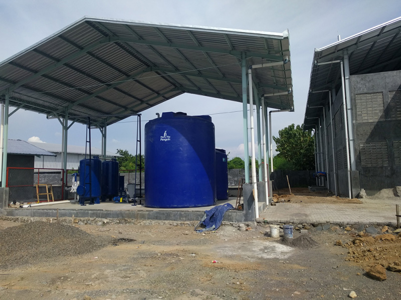
Hello friends, I have a 30 m^3 (30 tons) polyethylene water tank. I need to sense water level inside said tank to turn on/off pumps that supply it. I am familiar with the various sensing technologies (tuning forks, ultrasonic, radar, etc) but I am running into limitations due to the tank size. There is about 5m height difference between full and empty, which is too long for most models.

What is the most practical method for sensing/controlling the fill level of a large tank like this?
 
Replies continue below

Recommended for you

If you have exhausted all options (e.g. GWR as that will be my preference, etc), my suggestion would be:

For point measurement, you could install 2 off mobrey float switches (one for Hi Alarm and one for Lo Alarm) if you have two off nozzles at the side of the tank.

For continuous measurement, I would suggest two options:
1) Since it's an open tank (vented to atmosphere), you could potentially use a differential pressure padcell (both ABB and Emerson makes it) as long as you have nozzle connection available at the side of the tank where you want to set the lower range.

2) You could potentially use a bubble type level measurement system which is commonly used to measure seawater level in open caissons on offshore platform which is used for pump protection to ensure you are not running pump without any liquid in the range. Usually in offshore application you would use inert gas (e.g. utility gas or nitrogen) to inject bubbles in the caisson to avoid any potential build up of hazardous environment. I have seen Emerson 1151 transmitters used in this way and their product catalogue also gives bit of explanation how this works on page 2-20 (link:
You can do some more reading on
Hope this helps.
 
Assuming you want top entry
For point level I would look at Magnetrol displacer type you can get them with 3 different switches each one activated by a dedicated porcelain displacers suspended on thin SS wire. Just fix the displacers to the wire at the appropriate level .
Another type would be Jems reed switch with 3 magnetic floats/switches one at each level on 3/8" SS tubing. The tubing is made up of 3 short switch sections and extension pieces.
For continuous level a submersible level transmitter would give a 4 - 20 mA signal proportional to the immersion depth and your setpoints would be generated inside the control system.

Five meters is nothing for radar or Ultrasonic transmitters, another simple one would be capacitance with an insulated cable.
Float switches from Flygt are also quite popular but you need to make some arrangement to prevent the floats from tangling, work very well in still tanks, probably the cheapest of the lot.
 
5 meters is not too long for most type level detectors.

DP cell and transmitter is the 'go to' option as it's inexpensive and very common.

Ultrasonic would work fine. If it's a polyethylene tank, you can even mount some of them external to the tank (no need to have a nozzle), and it will still read the level.

If you do have a nozzle, or if it's an open top tank, non contact radar or ultrasonic will work...again 5 meters is NOT to long.


______________________________________________________________________________
This is normally the space where people post something insightful.
 
Hello again! After much datasheet reading I think I am somewhat settled on "Flowline EchoPod" (5.5m range, ultrasonic, by automation direct). It has a feature where it can do continuous (4..20mA) or act as a switch with several low voltage relays. I will mount it in a bulkhead fitting on top of the tank.

Are there any gotcha's that I should be aware of?

PS. Here is a picture of my tank. Actually, there are two - a small one 15m3 and a big one 30m3. Both hold water at different stages of purification.
tanks_resampled_zynhda.jpg
 
Rather an elaborate arrangement for a water tank, I'm referring to the roof.
Ultrasonics should work well, just be aware of the dead zone, probably about 12", try to put transducer where it's well away from water falling into tank.
How do you get access to the probe?
 
That entire area is for a water treatment system. Actually, now I'm wishing that I'd made walls in addition to the roof, because lots of rainwater gets in.

Ok, 12" of empty space at the top of tank should not be a problem. The sensor will be on the opposite side of the tank from the inlet.

To access the top of the tank I am planning to build a platform. Currently, we just climb up there with whatever means are available (scaffolding or aluminum ladders).
 
In general, ultrasonics have a problem with dished bottoms. Flat bottoms are OK. Installation instructions warn against mounting an ultrasonic at the center of a domed top, it should be elsewhere. Needs to be mounted so it shoots vertically, not an angle.

Most have a problem with condensation or frost on the face of the transducer; creates a Loss of Echo error. That happens when the liquid is warm but the tank is cold. The transducer face cools below dewpoint of the water vapor in the tank.

If it were me, I'd put a submersible pressure transmitter in from the top and be done with it.
 
Several posters proposed transmitters, ok assuming there is a PLC to interpret the signal the OP asked for switches.
The Magnetrol displacer type switches are easy to specify and use because all you have to adjust is the position of the displacer on the wire which costs virtually nothing.

I agree with Danw2 a submersible DP is the simplest transmitter if you have a control system, very cheap to install, no valves or flanges required. Capacitance is another simple installation with a cable probe but needs a ground reference.
 
A bit of an update :)

In the past few days I've had the first tries at the sensors. Easy to configure with their program (and usb stick). However, you have to disconnect the sensor first, ie no "live" debugging. Which means for any changes you have to climb on top of the tank and disconnect/reconnect all the little wires from the junction box... with a laptop in tow.

Anyhow, what I am finding is this: the sensor works great "at rest", ie when there's not water being added into the tank. (See pic). But when water is being added it seems the sensor loses the signal. Not sure whether it is because of the waves (maybe about an in inch or two in amplitude, not violent), or the column of incoming water (see pic).

I have the sensor mounted at 90 degrees (around the circumference of the tank) to the incoming nozzle. Using bulkhead fitting, flat surface.

Any help?
 
That's annoying!

Get a piece of cheap PVC to make an ultrasonic well. The water inside will, of course, match what's outside it provide a quiet smooth surface.

Other thoughts are that ultrasonic is sound. That huge hard-walled tank with water falling a mile down into it will be filled with ultrasonic sound including the reflected sound from the sensor. I think that's causing lots of un-reasonable returns to the receiver causing it to blank. Can the transmitted sound level be turned down causing less reflected power? Can the falling water be directed into a standpipe preventing any ripples and its noise?

Keith Cress
kcress -
 
You don't say what your sensor is so I assume it's ultrasonic, it looks like an easy application for a good quality ultrasonic.

Are you using Discrete outputs or Analog with a small PLC?

Your original post asked for a switch, has that requirement changed?
In the tank picture is that the pump suction we see?
Is that falling water?
 
Hi guys, sorry, been neglecting this post to work on pump controls, but actually I have some updates for this. But first, the questions.

Indeed, I am using an ultrasonic. Flowline dt-34. Is it considered good quality? Seems well made. It has some programmable relays which I utilize for low and high switches. (It also outputs 4..20mA on its power supply line, which is useful for debugging). But I do need the relays, as I am going PLC-free, heh.

Update. It now seems that the problem is electrical in nature. When drawing down the tanks with a pump (surface level completely calm, no falling water), the phantom relay activation/sticking still occurs. Sometimes the all relays of the sensor will suddely activate and then go off soon after. This is more rare, usually the relays just keep their state even if the switch condition has changed. The correct state is assumed immediately after all the pumps are stopped. This does not happen if draining the tank by gravity. Switching occurs at prescribed levels as would be expected. The 4..20 mA output does not die (eg go to some default value) during these phoenomena, instead it still shows a "reasonable" value and keeps changing. Seems like the problem is caused by having the signal cables near the power cables, yes? However, I am using shielded cable, 220 VAC signal level and have grounded the cable only on one end. The instrument ground and motor ground are tied together at the panel unfortunately.

Any ideas?

PS. About to test with the signal cable running through the air away from the motor cables.
 
I couldn't find DT-34 on the Flowline site, I assume its the DL-34 you have
Provided the cable is shielded properly you should be able to run the cable right beside the motor cable.
However are you running the AC motor controls in the same cable to the internal relays, that could be a problem

Perhaps try using a separate DC relay located back at the motor control point to control the motor in other words completely isolate the On/Off signal between the DL-34 and the motor.

I wouldn't go as far as to call the Flowline a high quality Ultrasonic but you may be able to get it working reliably.

If you think there is interference from splashing perhaps try to guide the falling water to run down the side of the tank or just operate over a shorter range at the top of tank.

Roy
 
Hi Roy, sorry for the slow reply. There was a break-in at our site mid this week. Thieves made off with a number of large power breakers and some smaller stuff from the outside control panels. So I've kind of been preoccupied with that :(

Anyways, the internal sensor relays are driving a coil of a panel-side relay (using 220 VAC as control signal). This coil, in turn, opens/closes contacts in the motor control circuit. I think this is the same as what you suggested.

Would using 24VDC as control signal instead of 220 VAC make any difference? Do you think common ground between motors and instruments may have anything to do with this?
 
Status
Not open for further replies.
Back
Top