Eng-Tips is the largest engineering community on the Internet

Intelligent Work Forums for Engineering Professionals

Sum of 3 Phase Conductor Magnetic Forces during Short Circuit

Status
Not open for further replies.

cuky2000

Electrical
Aug 18, 2001
2,122
0
36
DO
Knowing that the sum of the current is 0 during the fault, can we say if the sum of the magnetic forces is also 0 during a short circuit?
 
Replies continue below

Recommended for you

A magnetic field is created whenever an electric current flows through a conductor. This is because a moving electrical charge creates a magnetic field. The strength and direction of the magnetic field depend on the amount of current flowing and the direction of flow.

Magnetic force (F) is found by multiplication of the current amplitude (I) with the length of straight conductor (L) and the amplitude of a UNIFORM magnetic field (B) and the sine of the angle between current and magnetic field. Graphically, if the force is coming out of the page toward you, the magnetic field is going horizontally to the right and the current is flowing vertically downward.

Converting energy to motion for more than half a century
 
While the magnetic fields may cancel, the magnetic forces are dependant on the inverse square of the distances as well as on the current.
In a trefoil arrangement in a cable I expect that the forces will sum to zero.
With a flat conductor arrangement or with uneven spacing, while the currents and magnetic fields may sum to zero, I am not sure that the magnetic forces will sum to zero.

--------------------
Ohm's law
Not just a good idea;
It's the LAW!
 
The forces act on the conductors. Do not confuse forces with field strength.

--------------------
Ohm's law
Not just a good idea;
It's the LAW!
 

Thanks for your responses:

1) jghrist: a) What do you mean by the sum of magnetic forces? I mean the sum of magnetic forces in the three-phase conductors
∑F= F[sub]ab[/sub]+ F[sub]ac[/sub]+F[sub]ba[/sub]+F[sub]bc[/sub]+F[sub]ca[/sub]+F[sub]cb[/sub] =0[highlight #FCE94F]? (TBD)[/highlight]​
b) Forces on what? Between conductors

2) waross
a)In a trefoil arrangement in a cable I expect that the forces will [highlight #FCE94F]sum to zero.[/highlight]
With a flat conductor arrangement or with uneven spacing, while the currents and magnetic fields may sum to zero, I am not sure that the magnetic forces will sum to zero.(See below for comment)

3) FacEngrPE
a) The forces at some distance outside of the current paths (example trefoil) will [highlight #FCE94F]sum to zero[/highlight].
b) Close to the current carrying conductor and between the conductors the forces defiantly do not sum to zero. Please clarify.
==================================================================================================
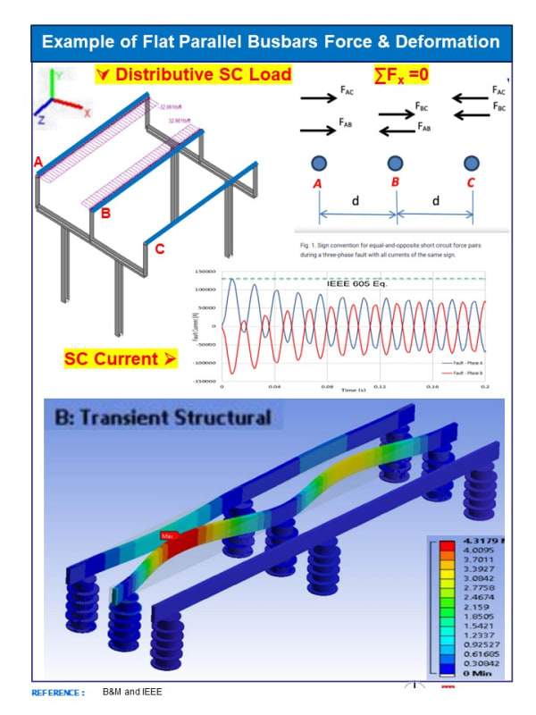
Below are a couple of sketches depicting the forces and deflection on a flat bus configuration and a trefoil cable from various sources. It does appear that the sum of forces [highlight #FCE94F]are zero.[/highlight]
 
 https://files.engineering.com/getfile.aspx?folder=d8b538d3-e2b9-4b8a-8bcd-d67bc932def6&file=Forces_on_Trefoil_Cable_Arrangement.pdf
Below is the sketch depicting the magnetic forces in an asymmetrical flat bus configuration

Force_Flat_Bus_bt9imz.jpg
 
cuky2000 said:
∑F= Fab+ Fac+Fba+Fbc+Fca+Fcb =0
Fab = -Fba. Same is true for all forces between conductors, therefore ∑F=0. There is no net force on the bundle of conductors, omly between conductors.

On your drawing of flat parallel busbars, there is no force on the 3-phase support caused by fault currents.
 
There is no net force on the bundle of conductors, omly between conductors.
I will accept that.
But
On your drawing of flat parallel busbars, there is no force on the 3-phase support caused by fault currents.
There are definitely forces on the individual phase conductors.
Note that the three phase support {Cross Arm} is not shown in the drawing. Only the single phase supports are shown.​

--------------------
Ohm's law
Not just a good idea;
It's the LAW!
 
waross said:
Note that the three phase support {Cross Arm} is not shown in the drawing. Only the single phase supports are shown.
I was referencing the top drawing, assuming the 4 vertical gray columns were the legs of the three-phase support.
 
Status
Not open for further replies.
Back
Top