Eng-Tips is the largest engineering community on the Internet

Intelligent Work Forums for Engineering Professionals

  • Congratulations waross on being selected by the Tek-Tips community for having the most helpful posts in the forums last week. Way to Go!

Super lightweight and low friction Pinion Spur Gear Design for high performance slot car racing

Status
Not open for further replies.

JVitor

Computer
Mar 5, 2019
8
0
0
BR
I would like to develop a new pinion for DC motors used in slot car racing competitions. The objective is to make a state-of-art pinion, focusing:
- high precision with lowest friction possible when used together with currently available nylon spur gears/crown gears;
- much lower weight than traditional steel and brass pinions, for a lower rotational mass in the motor shaft;
- very good strength to weight ratio, resulting in a long life pinion, suitable for sprint races but also for 24 hours endurance races

With this in mind and considering the specs below, I would like to receive suggestions to achieve the best project possible.

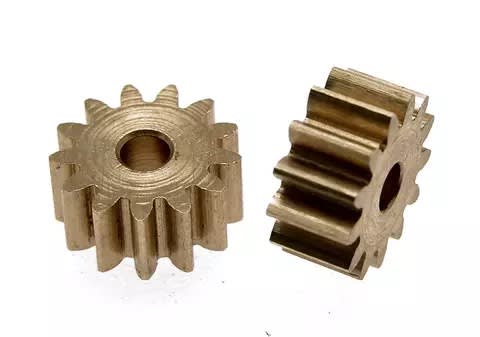
Type: Spur Gear Press-on with two beveled faces for easy pressing, hubless
Material: pure Titanium grade 5 6AL4V (suggestions??)
Coating: ??? Suggestions??
Modulus: 0.5mm Module Metric Spec
Teeth: 13
Outside diameter: 7.75mm
Width: 3.2mm
Hole: 2mm
Pitch: M50
Pressure Angle: 20

Thanks in advance guys for any help!

 
 https://files.engineering.com/getfile.aspx?folder=50831d71-f975-4292-9027-5b99bc1fb050&file=2C0B4E3B-3A0B-45D4-869D-41EE0B2711A0.jpeg
Replies continue below

Recommended for you

Here are some photos

E38D537D-F05F-4BC5-BD15-7726E4170C60_uriddd.jpg


B1BEB51F-448B-4BBA-A95D-8E1883706A2D_gwmhhx.jpg
I was thinking about making some holes in the face to reduce weight.

77A4333F-E6E3-4793-9EAC-09E6FFC2934A_oiwd7y.jpg
This is a type of grease used to lubricate the small (pinion) and big (nylon) spur gears.
 
The motor and axle centerlines appear to be non- parallel by several degrees. I suspect the mechanical efficiency of the gear power transmission suffers as a result.

================.==

..." very good strength to weight ratio, resulting in a long life pinion,..."
Is pinion strength really an issue? That is, do the teeth break off after a while ?

================.==

Less than half the pinion width is engaged with the spur gear in the picture you provided. I'd say that pinion could be lightened considerably by thinning, but leaving the "hub" full width to maintain the interference fit with the motor shaft.

================.==

Are there any trsces of that SuperLube left on the gear teeth after 10 minutes of running ?
 
Hi Tmoose, thanks for the reply!

Yes, the motor shaft and axle are slightly angled each other. It’s a “Anglewinder” positioning and I really don’t know for aure why a lot of slot car preps use this way. The other ways are “Sidewinder” (100% parallel - the way you should have suggested) and “Inline”

Yes, the pinions are used to wear and loose speed, or even break off some times!

I got your suggestion about a longer “hub center” and a thinner teeth. I think they are always bigger due to the various bigger crows available and the position chose of the motor for “a better anglewinder positioning”. I will consider it, good tip! What about the holes I suggested and the material/coating, what do you think?

Yes, some traces of the grease are always Left in the gears after races (and stay on as racers do not remove and clean gears often...)
 
I understand your primary concern is gear design, but what about a smooth running car? Low vibrations should help tires to get better traction for acceleration and to minimize spinouts. The car photo shows several setscrews that would/could cause unbalance. Consider highspeed balance of the motor with your new pinion and balanced tires, You might be surprised with the performance results.

Walt
 
Thanks Walt. Your appointments are absolutely right. Serious racers work hard in the alignment of the chassis with rear and front axle, besides the car body too. All the screws are tightened and loctite. Static wheel balancers are used and the foam tires are trued in small tire truers made specifically for the hobby. The armature of the motor are often tweaked too, like truing the commutator, changing brushes, balancing the motor shaft, cleaning and oiling the ball bearings, dampening the motor “pod” for lowest vibration possible... well, plenty of tricks to make a killer car! 😅
 
First of all you need a way to add or remove balance weight.
Second you need a fixture to hold motor without looseness so as to get repeatable data.
Third you need a balancing system that can measure vibration level at 1xSS, a tachometer signal (laser-optical, infrared-optical, or strobe-light) and be able to do single plane or two-plane balancing. The other method without need for speed signal is to use the 4-run method. Vibration sensor can be tiny accelerometer (about 2-grams), PVF accelerometer or microphone for non-contact measurements.

If you are trying to balance the motor within its case and with conventional power, then the focus would probably be optimizing balance at the pinion gear. If the rotor was removed and placed on a "suitable" spinner, then I would consider spinning it with a small air jet and optimize the armature balance. I have balanced a number of unusual machines, but not a tiny racer motor. It is a worthy challenge!

Search: slot car motor balancing
A lot of pictures and references, but no time to check them.

Walt
 
Thanks.

Madlya is a brazilian company that sells armature dynamic balancers, maybe I will try it at some point.

But my main focus with this topic would be to discuss the specifications of this new pinion and the best fabrication procedure for a very good precision. Watchmaker lathes and MIM technology are in my list. Where to produce? China only? And what about holes and geometry of the pinion to achieve best results?
 
Based on your diagram above, it looks like your blank could be turned on a swiss-style lathe and hobbed (maybe even made complete on one machine). There are countless machine shops across the world who can handle such a part (including in the US, in addition to China and other low cost regions (LCRs)), but they all (should) want a proper engineering drawing with materials and tolerances. Certainly think about how you want to mount the gear to the motor (close tolerance boss with a set screw hole? press fit with the motor shaft [while supporting the shaft from the other end of the motor]?) and create such a drawing.

MIM seems like overkill to even consider, based on hobbyist volumes. Just pay a job shop to machine it out of bar stock. It seems to me that the normally achieved tolerances should suffice.

Next, I'd think about controlling the mating gear, and creating something to keep the mesh in alignment.
 
"Certainly think about how you want to mount the gear to the motor (close tolerance boss with a set screw hole?" This would be a great vibration generator! I suggest shrink-fit mounting to keep unbalance mass eccentricity to a minimum. Grinding of gear sides can be used for trim balancing.

Walt
 
Thanks for the inputs. Yes, I’m still working in the final drawings. About pinion installation, it is always pressed with tools like that below.

74454124-94BC-4EA9-9F57-11111E565393_et90li.jpg
19EA31A8-FCC5-47B8-BE72-93F283FEEE96_hevqt6.jpg


Balancing the pinion would be good but by far is not a so rewarding job then making sure all chassis are well aligned, but ok, it’s always something to consider and it can be done in static magnet balancers.

But I’m still concerning about the material (6Al4V) and coating (Tin, TiCN). I’m not finding a lot of low cost shops that ate keen to do it in this material. I don’t know about galling and wear with this material. Please, need help in this matter, considering my objectives and of course the cost/benefit relation.
 
Status
Not open for further replies.
Back
Top