Eng-Tips is the largest engineering community on the Internet

Intelligent Work Forums for Engineering Professionals

Surface finish, warpage, and flatness on certain parts of a surface

Status
Not open for further replies.

Ramblin_Man

Mechanical
Jul 26, 2021
5
0
0
US
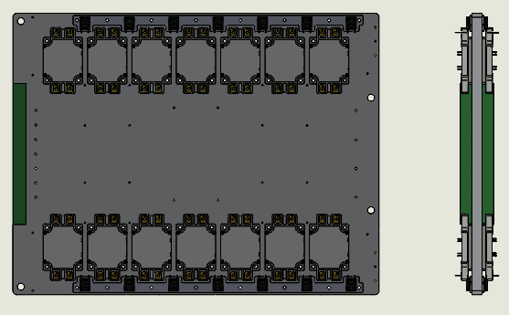
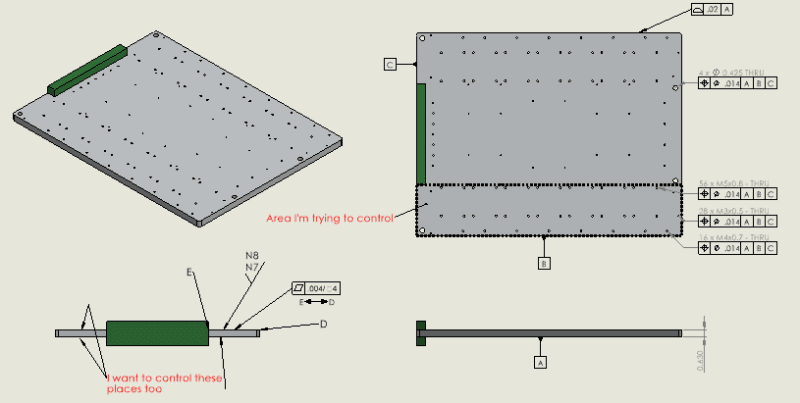
I'm designing a coldplate to mount IGBTs to. The IGBT manufacturer specifies a certain surface finish and "warpage" for the plate, 100um per 100mm. I'm assuming warpage is waviness (mfg is Japanese). I'm also assuming warpage is equivalent to flatness per area, which is how I'm trying to call it out.

I don't need the whole plate to meet this spec, just the areas that IGBTs will mount to. I've tried my best to call this out with GD&T per ASME standard but I'm not sure that its correct. They give no example of controlling a rectangular area of a surface, just a surface between two datum points. Also I have no idea how to apply surface finish to just a certain area of a surface, I see no example of attaching a surface finish callout to a GD&T callout like you do with say hole sizes. And then do that for three more areas without 6 extra datum. Drawing is attached. Thanks

Capture_twt4wg.png
 
Replies continue below

Recommended for you

Does it add significant cost to finish the entire part to the same flatness tolerance? Complex tolerances may cause loss due to interpretation errors.
 
That is a good point and what I may end up doing. But I do think it is an interesting question: how do you control just a part of a surface with GD&T. If I needed to mount just one device with a much smoother finish and tighter flatness, it would cost a lot to make the whole plate to that spec
 
To avoid confusion I would consider making the controlled surfaces slightly higher or lower than the uncontrolled so they would stand out both in the drawing and in the field.
 
Ramblin_Man,

Your question belongs in forum1103.

Flatness may be specified per unit area. In ASME Y14.5[‑]2009, see paragraph 5.4.2.2. The standard shows how to specify profile tolerances on limited areas. What you are showing is not in the standard, but I can make sense of it.

A tolerance of 0.1mm per 100mm does not sound all that difficult. As TugboatEng notes, specifying a pocket requires them to carefully mill it out.

How big are your transistors?

You do realise that plates are not very rigid, and they will take the shape of whatever it is you bolt them to, right? If your plate is not supported, the vibration mode shapes may not meet your flatness specifications.

--
JHG
 
drawoh,

I believe what I'm showing is in the standard, the flatness per area is 5.4.2.2 as you noted. Although I believe that means "over any 4" squared area on this surface, hold flatness to .004". Not "in this specific area on the surface". Which is what I want for that callout alone.

The between notation I used came from Fig. 8-7 "Specifying Profile of a Surface Between Points". Although I guess I'm not certain if you can use flatness the same way. And I don't see how you could constrain it further from another view, to say put just a rectangle on a surface.

TugboatEng points out some good practical solutions, but I was curious if GD&T offered a way to specify a roughness/ flatness spec to only a specific part of a surface. Fig 8-7 was the closest I could find. I mean I could just sketch out the area and dimension it, but I don't that is technically correct.

As for the transistors...
Capture2_uqg4gb.png


The plate is only supported 1" steel tabs that are bolted through the 4 large holes. It's somewhat hanging, and the supports are isolated with rubber washers. Hopefully the plate just conforms to the IGBTs.
 
Ramblin_Man,

You should define flatness relative to the size of your transistors. I take it they are way less than four inches in size.

Four support tabs define something other than a flat plane. Your plate will bend into whatever shape is defined by your four tabs. Rubber washers are surprisingly stiff, especially when you tighten your screws. Screws not tightened down hard, come loose.

Look into Sil-Pads. These provide a conformal thermal connection to your base plate, even if there is movement. This will get you around the flat plate.

--
JHG
 
Status
Not open for further replies.
Back
Top