Babak_k
Electrical
- Sep 26, 2017
- 4
Hi everyone
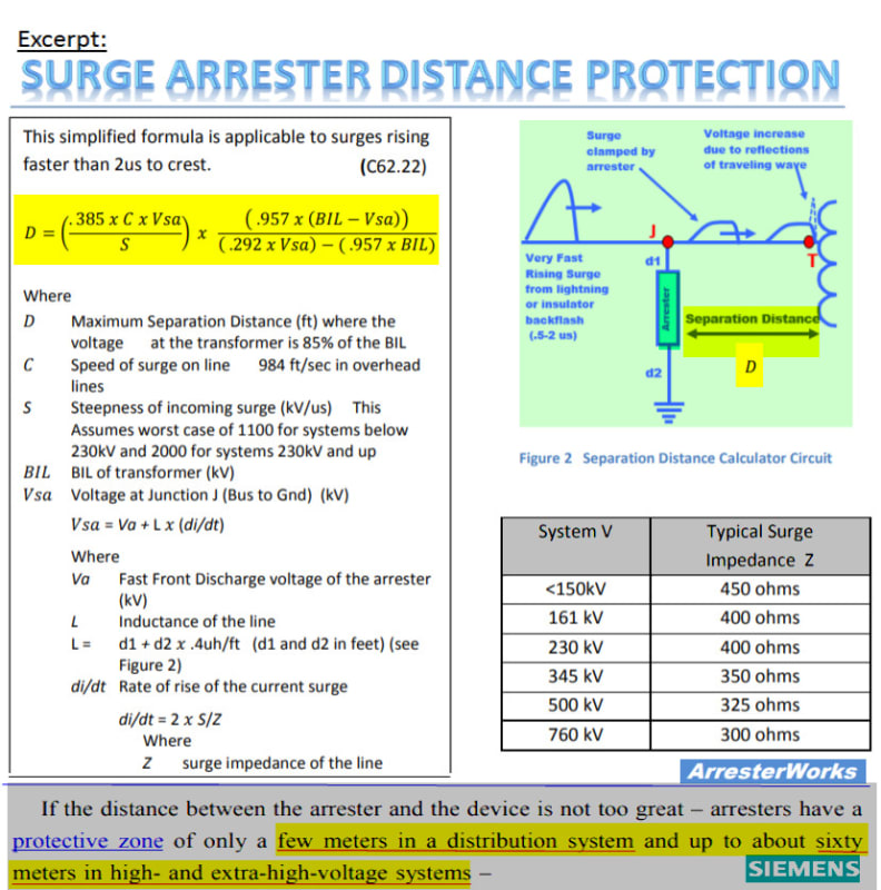
Regarding the installation of surge arrester, I tried to find some documents or standards but as they are not free my attempt was without results.
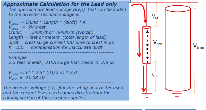
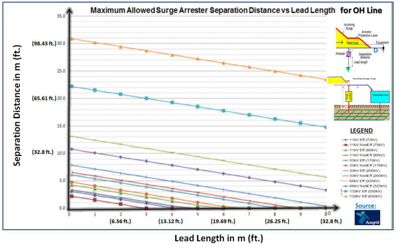
In a power plant we have seen the surge arrester on the transformer have the earthing cable with the long of 10 m. the type of surge arrester is:
The INZP” type arrester are heavy duty distribution class surge arrester. These
are gapless design incorporating highly non-linear metal oxide varistor, with a
discharge rated current of 10 kA. The housing can be polimeric INZP type. The
housing is polimeric
I am not specialist for this topic. The question is that is the cable too long for the surge arrester? and can make the voltage over than the tolerance of the device? and how can I find it that the installation of device is under the standard conditions.


