Continue to Site

Eng-Tips is the largest engineering community on the Internet

Intelligent Work Forums for Engineering Professionals

  • Congratulations SSS148 on being selected by the Eng-Tips community for having the most helpful posts in the forums last week. Way to Go!

Suspended garage slab over basement 1

Status
Not open for further replies.

Nerbie97

Civil/Environmental
Apr 16, 2022
9
Hi all,

A friend is building a new house, and has approached me to design his suspended slab which will support a two-gar garage above. The area below will be storage space. The plan dimensions are roughly 5500mm x 6000mm and he does not want to have any columns interrupting his space below. We are in Eastern Canada.

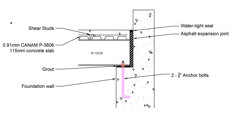
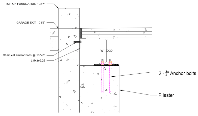
The garage is surrounded by foundation walls which sit 12" above the final top of slab elevation. Initially, I had done a quick check assuming a concrete slab - with & without concrete beams - and we found that it'd be too expensive to meet deflection criteria. I explored some options & read the few posts on elevated garage slabs here, evaluated some other options with the client & currently we are going with a slab on steel deck. The 6000mm span will essentially be cut in 3, for three (roughly even) spans of <2000mm. Instead of bearing the slab on the foundation wall, I'm opting to place two beams on the extremities as end-bearing beams & slightly prolong the slab to finally sit on an angle anchored in to the wall. I figure this way, only a check for the shear capacity of the angle is in order for the foundation walls.

I understand the challenges with steel construction below a garage - the client understands this very well as well and an effort will be made to prevent water from seeping in through the perimeter joints. Galvanized steel components are also in the question.

My principal concerns at the moment are water considerations which is why I am having doubts about the choice of steel deck. Would specifying galvanized steel & detailing a water-tight expansion/flexible joint around the perimeter of the slab be sufficient to ensure the performance of this structure? In a previous post, a user completely ignored the decks contribution (over the long-term) as they assumed salt would eat up the deck below over time.

Furthermore, how would one design for drainage in an elevated slab? I wanted to put a drainage canal at the front of the garage (right behind the door) and give the whole garage a 3" slope towards it. But, I am worried about a car's wheel load over the canal. How would you support the canal from below?

Also, judging based on past threads here, many have used this option (in various jurisdictions) - I can't seem to find any resources which indicate if this construction is permitted with regard to fire safety considerations.

Attached are two preliminary details I have (very roughly) drawn.

I would appreciate any and all constructive comments. Thank you.

FIL2_qgq6wv.png
FIL1_cgwomh.png
 
Replies continue below

Recommended for you

What slab thickness did you get with the 5500x6000, I would have thought a flat suspended two way slab would have been cost effective compared to the steel detailing.
 
Another possibility is to use hollow core slabs spanning 6.0m and bearing on concrete foundation walls. The drainage canal could be formed by dropping one unit down to the required depth and casting the channel shape with C.I.P. concrete, placed along with topping. Wheel loads could be supported by steel grating spanning the canal, possibly galvanized or epoxy painted.

Steel deck and steel shapes below the slab could present a corrosion problem over time. Cars in Quebec bring in lots of snow in winter months.

BA
 
Agree with rowingengineer. It might also be cost effective to introduce a shallow concrete beam in one direction to bisect the space. That would take less headroom than W12 beams.

Agree with BAretired about corrosion issues.
 
Thank you very much for your inputs rowingengineer, BAretired, hokie66.

I am re-visiting my concrete calculations, and admittedly I may have subconsciously favored the steel construction for the following reasons:

[ul]
[li]I am much more comfortable with steel's behavior as a material and its' analysis under load (aren't we all?).[/li]
[li]The client got a rough bid for the slab (just based on plan dimensions & free-spanning, no columns) from his foundation contractor - just slightly south of $30,000CAD.[/li]
[li]I was asked only to design the slab itself & wanted as little as possible to not mix in an elaborate foundation wall check. A slab supported as shown in the details would induce virtually no moment on the foundation walls. (On this point, I may lack understanding of the connection behavior between a concrete slab & wall - for a two-way design (assuming no beam), shall I consider the slab connected to the foundation wall as fixed?[/li]
[/ul]

 
I would just sit the slab on top of the wall. Although there will be a degree of fixity, my approach would be to consider the slab pinned at the edges, and just provide a nominal amount of top bars. The curb above the slab can be either cast monolithically with the slab, or separately.
 
Hmm. Okay. I see it as three separate pours - 1. Foundation walls, with dowels/development bars in place at top of wall, 2. Slab, 3. Curb.

I'm having trouble wrapping my head around the effect the slab has on the wall itself. I understand that assuming the slab as pinned will provide for a more conservative design, and I have no trouble doing that analysis, however, doesn't providing fixity in terms of dowels between the wall & slab induce a moment in the foundation wall?

Assuming pinned for the slab design and then a certain moment transfer to the wall could be an option (and as I understand, the only option). Any way to avoid the wall moment check?
 
I assume it will be a reinforced concrete wall. Not sure why you would want to avoid the wall moment check. I take it the wall will be a basement wall, so subject to soil pressure. The gravity load from the floor should only increase the bending slightly.
 
You're right, it will be a reinforced concrete wall. Except the houses around here have very minimal reinforcement in the walls themselves, which is why I wanted to avoid relying on the wall for any other resistance besides compression in the first place (hence the idea of beams on pilasters supporting a steel deck or embedded steel beams).
 
hokie66, I read your response in an older thread at
hokie66 said:
Leftwow,
That was not my advice. Some fixity needs to be allowed for both, but neither is either fixed or pinned. For slabs, we analyze as pinned, then reinforce for nominal fixity. For walls, we use a degree of eccentricity for the vertical load, then add the out of plane loading.

From what I understand, you're suggesting sort of the same thing here. I shall design the slab reinforcement assuming pinned connection to the four walls, and design the foundation walls as if the slab were fixed - but not taking the full moment that a fixed slab connection would induce.

I did a (very conservative) check yesterday evening assuming a one-way slab spanning in the short direction, then assuming that same steel in the longer span - it's just too much steel & concrete. I kept getting 20M's at 6" c/c - governed by the NBCC prescribed 54 kN point load. (On that note, I'm erring on the side of caution as my friend is in construction and may be parking his 3500 in the garage one day).

Will do the two-way slab check tonight (since that's how the slab will act, after all) & return with results.
 
You have understood my suggestions, and the earlier one is consistent with what I suggested above.

A slab supported on 4 sides works very differently than a flat slab supported by columns, so your conservative check is too conservative. Obtain the actual moments in each direction, and your design will be more to your liking.
 
One detail to pay attention to: the corners of your slab will tend to warp, so some top steel is especially required there.
 
Nerbie97 said:
I kept getting 20M's at 6" c/c - governed by the NBCC prescribed 54 kN point load. (On that note, I'm erring on the side of caution as my friend is in construction and may be parking his 3500 in the garage one day).

Even if you want to be conservative and allow for his 3500 to be parked in there (this is conservative because it probably doesn't fit), I wouldn't use the 54kN point load. Ram 3500 GVW is about 5000kg so you could go with the 36kN point load. Using that, you should be able to achieve this slab with 15M at a very reasonable spacing using an 8" structural slab. What we've done previously on similar projects is an 8" slab (sometimes 9", sometimes 10"), waterproofing membrane on top of that (specified by the architect), then maximum 3" or 4" of concrete topping above that as a wearing surface.

Designed as pinned at all supports, detailed with hooks to prevent cracking. Walls are typically backfilled so any moment that is induced in that direction into the wall is just reducing the moment from the soil.
 
ryaneng said:
Ram 3500 GVW is about 5000kg so you could go with the 36kN point load. Using that, you should be able to achieve this slab with 15M at a very reasonable spacing using an 8" structural slab.

It really is the 54kN point load - using the moment coefficient method prescribed in CSA A23.3-19 (Annexe B - Informative) (I believe ACI also used to offer this method for two-way slabs) I achieve a moment of 21 kn-m in my short span with a factored load of 17.5kPa. (8.5 kPa dead, 9.0 kPa live, factored). In which case you'd be right, 15M's even spaced at 350mm c/c would be sufficient to resist this moment.

It really is the point load. I don't feel too comfortable designing for less than the NBCC-prescribed live load, however, it needs to make sense. Seeing as though the moment coefficient method is written out for uniform loads, and I couldn't find a similar method (besides the direct-design method) for concentrated loads, I used an equivalent distributed load which would give me the same maximum moment on my BMD and computed the moments with that distributed load.

ryaneng said:
What we've done previously on similar projects is an 8" slab (sometimes 9", sometimes 10"), waterproofing membrane on top of that (specified by the architect), then maximum 3" or 4" of concrete topping above that as a wearing surface.

This sounds like a good idea.
 
hokie66 said:
One detail to pay attention to: the corners of your slab will tend to warp, so some top steel is especially required there.

Thankfully I did an inspection earlier this year which exhibited exactly this phenomenon - safe to say it stuck with me enough to remember. Thanks.
 
Nerbie97 said:
It really is the point load. I don't feel too comfortable designing for less than the NBCC-prescribed live load, however, it needs to make sense.

Why do you think this needs to be designed for vehicles over 9000kg GVW. I don't think a 3500 is in that range.
 
Does a 3500 fit in the garage? We have built homes to fit a 3500, but it needs a larger door and longer slab. Your 6m OA length suggests it might not. Your mass seems high as well since you cannot fit it inside with a loaded trailer that adds to the rear axles.

TABLE_firvqj.png
 
Hmm.
You guys are correct.
I initially chose the 54kN as I understood the space as a "driveway and sidewalk over areaways and basements." Upon further reading, those areas apply to areas such as parking garages, driveways, curbs & sidewalks physically accessible to large vehicles like garbage and firetrucks. Which is not the case here.
After realizing & reducing my live load from 12.0 kPa for these areas, to 6.0 kPa (for garages for vehicles between 4-9000kg), I chose to keep the original point load requirement since 54kN is conservative yet not too far off what (stupidly) jacking the back of a 3500 with a 1-ton pallet in the bed would produce.
Alas, it is now apparent to me that that is much too conservative & I shall simply follow the NBCC requirements for garages for vehicles between 4-9000kg (point load of 36kN).

Thank you.
 
Status
Not open for further replies.

Part and Inventory Search

Sponsor