frusciante8989
Electrical
Hi guys, I have a problem with designing a channel switching system for a tube amplifier. I usually go for relays with flywheel diodes, with the relay coil ground connected to the switch. However, I implemented this solution in a 3 channel amp and I can not tolerate the popping noise. I looked around the web and it seems that the best way would be to use a muting circuit (some also suggest to use an optocoupler). My specs/requirements are:
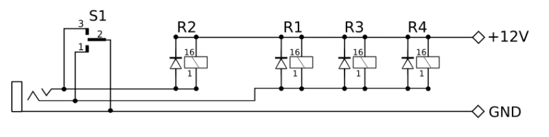
1) the amps has three channels with separate gains, masters and tonestacks.
2) The are 4 relays. R1, R3, R4 are tied together, and R2 is separate.
3) when all relays are off, the mode is "Crunch". When R1, R3, and R4 are on, "Lead" mode is on. When R2 is on, "Clean" mode is on.
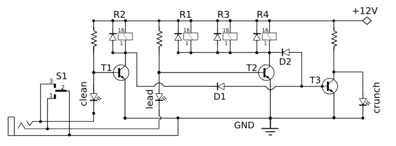
Right now, this is triggered with 3 position switch from the front panel of the amp. It works, but it pops. My idea is to keep the front panel switch, add muting, add LEDs (currently not present), and add a footswitch, possibly using a 5 pin DIN port. My current footswitch works with a stereo jack but has only two footswitches, and to change from CRUNCH to LEAD I have to press one of the buttons twice. I'd ideally like to have three separate buttons for each channel.
Do you guys have any idea on the circuit that is most suitable for this application? I've attached a sample circuit that I drew using NPN switching (which is a completely topic for me) instead of the current system... I also attached the signal path for the amp. What do you think?
I've always built single channel tube amps so far, so this is new territory for me. Forgive me for my noobiness in the area, but this is quite exciting to learn")
Thanks for the help.
Current system
Proposed system with LEDs and with cure for POP
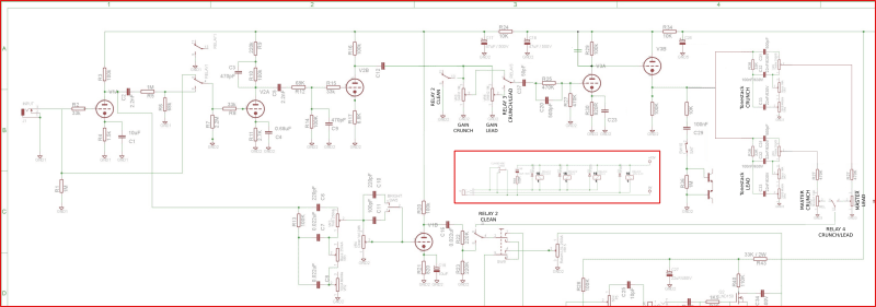
Signal path in the amp
1) the amps has three channels with separate gains, masters and tonestacks.
2) The are 4 relays. R1, R3, R4 are tied together, and R2 is separate.
3) when all relays are off, the mode is "Crunch". When R1, R3, and R4 are on, "Lead" mode is on. When R2 is on, "Clean" mode is on.
Right now, this is triggered with 3 position switch from the front panel of the amp. It works, but it pops. My idea is to keep the front panel switch, add muting, add LEDs (currently not present), and add a footswitch, possibly using a 5 pin DIN port. My current footswitch works with a stereo jack but has only two footswitches, and to change from CRUNCH to LEAD I have to press one of the buttons twice. I'd ideally like to have three separate buttons for each channel.
Do you guys have any idea on the circuit that is most suitable for this application? I've attached a sample circuit that I drew using NPN switching (which is a completely topic for me) instead of the current system... I also attached the signal path for the amp. What do you think?
I've always built single channel tube amps so far, so this is new territory for me. Forgive me for my noobiness in the area, but this is quite exciting to learn
Thanks for the help.
Current system
Proposed system with LEDs and with cure for POP
Signal path in the amp