Eng-Tips is the largest engineering community on the Internet

Intelligent Work Forums for Engineering Professionals

Sync Motor Out of Phase Syncing damaging Diode Wheel

Status
Not open for further replies.

rockman7892

Electrical
Apr 7, 2008
1,147
0
0
US
Customer has a 17,400hp 13.8kV brushless synchronous motor that is driving a centrifugal compressor. This motor is fed from a dedicated feeder breaker that is part of a 13.8kV Switchgear lineup. The motor has a 2200 HP Induction Pony Motor that is used for starting the synchronous motor and once the motor is started and the exciter field applied the feeder breaker is closed to sync the motor to the utility power (switchgear main bus).

It is being reported that they are frequently blowing diodes in the diode wheel of the rotating exciter which is occurring most of the time during starting. It is being suspected that when the feeder breaker is closing its slightly out of sync with utility voltage which is causing a voltage transient which is seen in the stator of the motor and then reflected onto the rotating exciter of the motor and causing the damage to the diodes in diode wheel. There is basic snyc check setup across the breaker however its operation and accuracy are now in question.

My question: Is it possible for a voltage transient from out of phase syncing (or any other voltage transient) to be reflected from the motors stator onto the rotating exciter? In this case I believe it would have to be reflected from the stator onto the actual rotor and then make its way into the diode bridge somehow? Is this possible? I also thought that most diode wheels had some sort of resistor or snubber design to mitigate such transients during starting?

As part of a side question, it is my understanding that synchronous motors can also be started as induction motors and then when they are up to speed the field is applied? In such cases the utility voltage is used for starting and thus breaker syncing is not in the picture. Is there a particular size or application which warrants starting motor with a pony motor and essentially starting it as a generator before syncing to utility? Does the field get applied after the pony motor brings motor up to a certain speed?
 
Replies continue below

Recommended for you

A sync check won't do the job.
Google "Polarized Field Frequency Relay"


--------------------
Ohm's law
Not just a good idea;
It's the LAW!
 
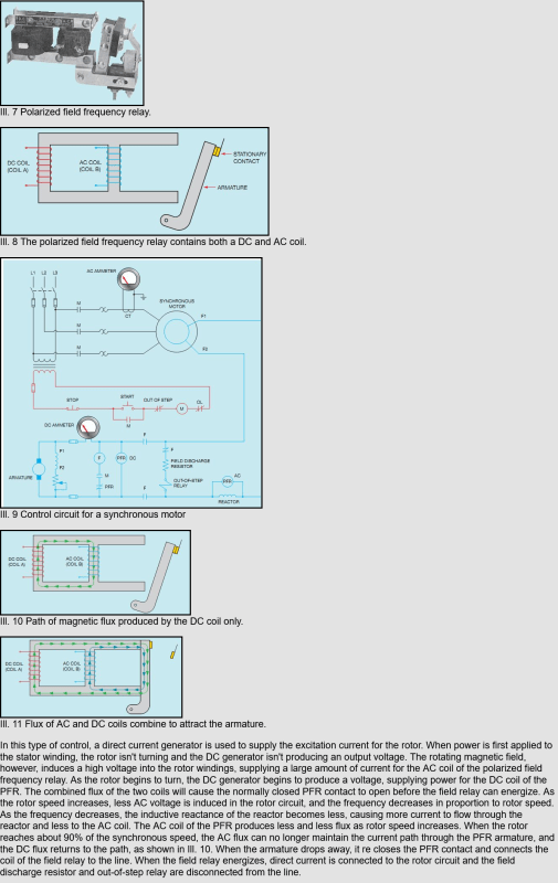
Screenshot_2024-02-27_at_07-34-28_Industrial_Motor_Control_Synchronous_Motors_wupxnp.png


Polarized Field Frequency Relay

--------------------
Ohm's law
Not just a good idea;
It's the LAW!
 
rockman7892 There are three basic ways to start a synchronous motor. One is to undergo a "line start" - which is typically where the main breaker feeding the stator winding is closed and the machine comes up to near synchronous speed (as an induction machine) prior to engaging the main rotor field excitation. Another is to start the motor on a drive, which requires that the excitation be applied prior to closing the main breaker, because the synchronous rotor is intended to remain in synchronism throughout the acceleration to "normal" running speed.

The third option is to use a pony motor of some sort to spin up the synchronous rotor to near synchronous speed. At this point, close the main breaker to synchronize the stator with the main power supply. THEN close the contactor for the main field excitation (at full rated field current) to "lock" the synchronous motor into synchronism. And finally disengage the pony motor.

Converting energy to motion for more than half a century
 
Your third method needs a Polarized Field Frequency or electronic equivalent to avoid damage.
The window of permission on a sync check relay may be too large for safely applying excitation.

--------------------
Ohm's law
Not just a good idea;
It's the LAW!
 
My understanding, and have seen this before with large unbalanced voltages, is if the machine rotor is rotating relative to the grid magnetic field, it impresses an AC voltage on the field (a hard sync for example, or out of step) like an induction machine. The bridge will block one half of the AC wave. If the impressed voltage is high enough I could see that the reverse voltage could potentially exceed the breakdown voltage of the diode.

I haven’t done an exhaustive search but I’ve seen at least one brushless design where the manufacturer installed a surge arrestor on the rotating diode bridge to protect the diodes from overvoltage. The field relay waross mentions would be for this purpose. Static exciters pretty much always have a set of field surge arrestors.
 
Is it possible for a voltage transient from out of phase syncing (or any other voltage transient) to be reflected from the motors stator onto the rotating exciter?

Yes, it is. A slipped pole, for example, will cause the the field current to reverse.
 
Thanks for the responses.

From what I've read and understand the Polarized Field Frequency Relay (PFR) is needed in both applications for starting as an induction motor and starting with pony motor since in both cases motor will have stator windings energized and thus induce an AC voltage in rotor. The purpose of the PFR is to ensure that the AC field in rotor had diminished enough before applying DC field to rotor. Do I have that correct?

Is the application of DC filed to rotor while there is still a high AC voltage present on rotor lead to voltage spikes in the rotor? Trying to understand the physics of that?

Also when DC field is applied does rotor automatically stay in sync with rotating field in stator? I'm just trying to picture when rotor is rotating and a new magnetic field is applied what are the impacts of that.

Is the purpose of the pony motor in such cases to reduce starting current as opposed to starting across the line as induction motor since pony motor will get motor up to near speed and thus reduce the starting speed/torque curve for motor starting? Motor is still technically starting as an induction motor?
 
I've never seen a PFR used on a brushless machine.

The field winding of a synchronous motor has an AC voltage that is inversely proportional to the motor speed while it is starting before the field is applied. The voltage can be very high if it's not clamped with some type of device, typically a resistor is used to keep it below the voltage ratings of the semiconductors in the exciter.

I'd have to believe that transitioning it to line power before applying the field would be the least stressful on the equipment.

A synchronous motor with full field applied will produce a voltage a fair bit higher than it's rated voltage. Like 120-130%. You should both match the phase and control the field current to match the voltage level if you want to close it onto line power with the field applied first.
 
Hello Lionel.
I mentioned PFR or electronic equivalent.
The PFR energizes the field when the slip and the rotor position relative to the rotating field are both suitable for smooth pull in to sync.
Brushless synchronous motors will have a rotating, electronic circuit to perform the same function.
This circuit, by whatever name, may have failed.

--------------------
Ohm's law
Not just a good idea;
It's the LAW!
 
There is a reason that rotating machine standards specify that the synchronous machine rotors be tested at 10 times the rated voltage while the stator is tested only at twice the rated voltage + 1 KV for new or rewound machines. Because out of phase synchronization induces much higher voltages in the rotor than in the stator while also subjecting it to high mechanical stresses. The rotor should be energized only when the rotor is close to the synchronous speed and not during the entire start duration.

Check the PIV of your diodes. Typically, they should be 1000 V and above.

Muthu
 
Brushless synchronous motors will have a rotating, electronic circuit to perform the same function.

I might have seen 100 or more brushless motors by now that do not. They simply go brushless alternator - rectifier - field. When the exciter field is applied, whatever voltage gets generated is rectified and goes to motor field. The only control on the rotor is for the FDR or even just for SCRs to short the field opposite direction of the rectifier diodes.
 
The Syncrite isn't a WEG product, it's an Electric Machinery (which was purchased by WEG several years ago) product.

GE and Westinghouse (now TECO Westinghouse) have similar designs doing similar things. The biggest difference between GE and nearly everyone else is that they often use a crowbar circuit to force the field voltage to zero in case of a fault condition, where everyone else just dumps the energy to the field discharge resistor.

Converting energy to motion for more than half a century
 
Electric Machinery developed and held the patent on the first Polarized Field Frequency Relay.
The Sybc-Rite performs the same function on brushless synchronous motors.


--------------------
Ohm's law
Not just a good idea;
It's the LAW!
 
Status
Not open for further replies.
Back
Top