Hi,
People don't often post about solved problems, but here I am. I'm hoping this will be a fun post for the group. I think have solved a problem and struggling to figure out why I had to spend 7 years working on it when it was so obvious at the end. Several years ago, I was trying to solve a problem that had daunted me for years, came up with a solution, and moved on. Since then I've looked back at what I did and wondered "why hasn't anybody ever thought of that before?"
I can't find any patents for the device, and I can't find any articles in journals (IEEE) that I have searched.
Once I settled on the idea, it seemed "obvious" to me which breaks one of the principles of the patent - but then how come nobody does it...?
I'm not really interested in getting a patent - the rigamarole, the cost, and the futility of trying to defend it are all disincentives. But I really do think I should publish about it - if this truly is a unique idea. It would be nice to have a useful article to my credit. It's an idea I would like to share, but I want to find out if it's really a new idea, first. So I'd like to formulate a little test and see if anybody else finds this "obvious" with a few clues and conditions. If I just told you, then any smarty pants can come on and say "yes it's obvious" and publish it for themselves.
I promise to tell the rest of my story but only if there's interest, or if the answer is so obvious that somebody guesses right away. I'm a mechanical engineer with an interest in all engineering disciplines, dabbling in many others, so I could have missed an obvious solution or the one I came up with is indeed obvious and electrical engineers do it all the time (for some reason they don't talk about it?).
First I have a confession to make: I built a wind turbine. (No apologies to those who are offended) I built it out of personal interest but I have been approached by a person who wants to buy one just like it from me. Never considered this a commercial product before, but if I am going to look at it that way, then I need to work on some of the control and safety aspects.
Its design is fairly elaborate but its construction is simple. It has had good performance for many years, but the obvious missing piece of information is how fast it's turning. I needed a tachometer.
Options that I considered: encoder, hall sensors, tach generator, frequency measurements on AC powerline.
Location of the turbine is at the top of the tower, which is stating the obvious. I point it out because that makes adding little finnicky gadgets difficult. To support some types of tachometer, signal wires going up the tower are needed. Some even need their own power supply to work. Sure, I can add little signal wires but it won't be robust. To make it robust would be costly. Slip rings, custom cables, etc. This wind turbine has run well for almost 10 years without a flaw and I would hate to have a thing like a tachometer in it that forces maintenance yearly. Despite the reluctance, I did actually install a hall sensor into it (two for redundancy) and started bench-testing but I got really frustrated with the difficulty of re-designing the mount of the generator itself to accommodate either a slip-ring assembly that would somehow pass small-signal currents without noise of their own.
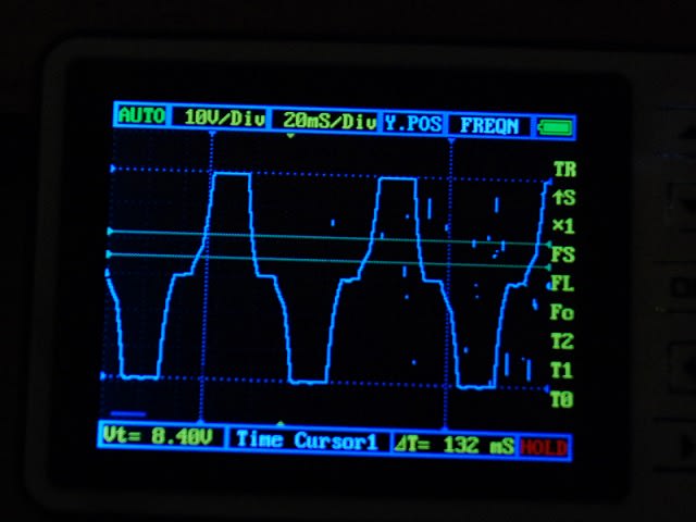
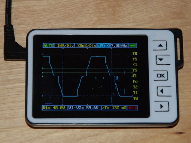
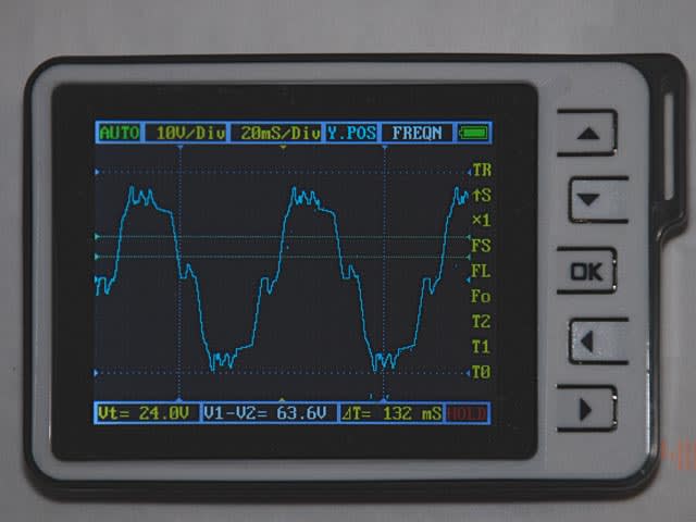
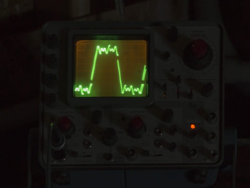
I resolved to try to build a tachometer that relies only on the AC on the powerlines. However, the turbine is a customized 3-phase generator and the output is rectified to charge batteries. Off-grid stuff. The rotor blades are direct-drive on the generator, with a variable speed. The speed varies from 0 to 150 RPM (charge current cut-in) to about 400 to 500 RPM where the tail's furling mechanism folds everything out of the wind for protection. The AC coming from the turbine is definitely not a sine wave. It's more of a clipped trapezoid with harmonics and noise. The variable speed and DC rectifier switching puts spikes in that vary in intensity at different speeds. There are also flat spots crossing zero that you can see on an oscilloscope. It's a mess. This does not affect the power output of the turbine. Remember, the load is a DC rectifier, so the noise and spikes are inconsequential to power conversion.
I built the obvious thing with a LM2917 IC and tested several variations but they all failed. The 2917 got its input from one of the three AC lines from the generator to the rectifiers. It would pick up the harmonics at certain speeds, the baseline at others. I tried filtering but that was very tricky to get right. I thought I was close but then made a change in the the generator wiring and found myself back at the beginning. I tried an optoisolator and fed the pulses to a microcontroller and got exactly the same thing. The microcontroller could be programmed with some extra code to "guess" the bad data but always discarded huge ranges of records.
When I solved it, I was able to dispense with any filtering at all. I still used a microcontroller, so I was able to build a more elaborate data-logger around it, so I now have current, voltage temperature and a number of other things measured simultaneously. Every second if I want a mountain of data. Sampling and averaging is easy in the microcontroller programs.
So now that I've described my failures trying to solve it, before I had my "great idea", what would you do? Faced with the need for a tachometer, how would you get a good solid signal proportional to the speed of a machine like this?
People don't often post about solved problems, but here I am. I'm hoping this will be a fun post for the group. I think have solved a problem and struggling to figure out why I had to spend 7 years working on it when it was so obvious at the end. Several years ago, I was trying to solve a problem that had daunted me for years, came up with a solution, and moved on. Since then I've looked back at what I did and wondered "why hasn't anybody ever thought of that before?"
I can't find any patents for the device, and I can't find any articles in journals (IEEE) that I have searched.
Once I settled on the idea, it seemed "obvious" to me which breaks one of the principles of the patent - but then how come nobody does it...?
I'm not really interested in getting a patent - the rigamarole, the cost, and the futility of trying to defend it are all disincentives. But I really do think I should publish about it - if this truly is a unique idea. It would be nice to have a useful article to my credit. It's an idea I would like to share, but I want to find out if it's really a new idea, first. So I'd like to formulate a little test and see if anybody else finds this "obvious" with a few clues and conditions. If I just told you, then any smarty pants can come on and say "yes it's obvious" and publish it for themselves.
I promise to tell the rest of my story but only if there's interest, or if the answer is so obvious that somebody guesses right away. I'm a mechanical engineer with an interest in all engineering disciplines, dabbling in many others, so I could have missed an obvious solution or the one I came up with is indeed obvious and electrical engineers do it all the time (for some reason they don't talk about it?).
First I have a confession to make: I built a wind turbine. (No apologies to those who are offended) I built it out of personal interest but I have been approached by a person who wants to buy one just like it from me. Never considered this a commercial product before, but if I am going to look at it that way, then I need to work on some of the control and safety aspects.
Its design is fairly elaborate but its construction is simple. It has had good performance for many years, but the obvious missing piece of information is how fast it's turning. I needed a tachometer.
Options that I considered: encoder, hall sensors, tach generator, frequency measurements on AC powerline.
Location of the turbine is at the top of the tower, which is stating the obvious. I point it out because that makes adding little finnicky gadgets difficult. To support some types of tachometer, signal wires going up the tower are needed. Some even need their own power supply to work. Sure, I can add little signal wires but it won't be robust. To make it robust would be costly. Slip rings, custom cables, etc. This wind turbine has run well for almost 10 years without a flaw and I would hate to have a thing like a tachometer in it that forces maintenance yearly. Despite the reluctance, I did actually install a hall sensor into it (two for redundancy) and started bench-testing but I got really frustrated with the difficulty of re-designing the mount of the generator itself to accommodate either a slip-ring assembly that would somehow pass small-signal currents without noise of their own.
I resolved to try to build a tachometer that relies only on the AC on the powerlines. However, the turbine is a customized 3-phase generator and the output is rectified to charge batteries. Off-grid stuff. The rotor blades are direct-drive on the generator, with a variable speed. The speed varies from 0 to 150 RPM (charge current cut-in) to about 400 to 500 RPM where the tail's furling mechanism folds everything out of the wind for protection. The AC coming from the turbine is definitely not a sine wave. It's more of a clipped trapezoid with harmonics and noise. The variable speed and DC rectifier switching puts spikes in that vary in intensity at different speeds. There are also flat spots crossing zero that you can see on an oscilloscope. It's a mess. This does not affect the power output of the turbine. Remember, the load is a DC rectifier, so the noise and spikes are inconsequential to power conversion.
I built the obvious thing with a LM2917 IC and tested several variations but they all failed. The 2917 got its input from one of the three AC lines from the generator to the rectifiers. It would pick up the harmonics at certain speeds, the baseline at others. I tried filtering but that was very tricky to get right. I thought I was close but then made a change in the the generator wiring and found myself back at the beginning. I tried an optoisolator and fed the pulses to a microcontroller and got exactly the same thing. The microcontroller could be programmed with some extra code to "guess" the bad data but always discarded huge ranges of records.
When I solved it, I was able to dispense with any filtering at all. I still used a microcontroller, so I was able to build a more elaborate data-logger around it, so I now have current, voltage temperature and a number of other things measured simultaneously. Every second if I want a mountain of data. Sampling and averaging is easy in the microcontroller programs.
So now that I've described my failures trying to solve it, before I had my "great idea", what would you do? Faced with the need for a tachometer, how would you get a good solid signal proportional to the speed of a machine like this?