Eng-Tips is the largest engineering community on the Internet

Intelligent Work Forums for Engineering Professionals

  • Congratulations waross on being selected by the Tek-Tips community for having the most helpful posts in the forums last week. Way to Go!

Tank Drain Flow Rate Into Pipe

Status
Not open for further replies.

GGriffin

Mechanical
Apr 11, 2018
7
0
0
CA
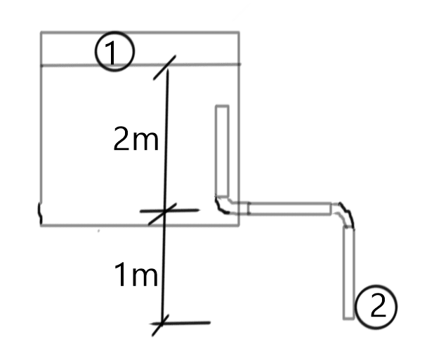
So I know this is something that's been asked before, but I haven't seen any real considerations for the pipe that a tank will drain into.

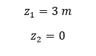
I have a 2.5" drain line out of the side of a tank, so using Q = a*Cd*(2gh)^0.5;

a = 5.45 in^2 = 0.00352 m^2
Cd = borda outlet = 0.51
h = 2m

So, Q = 0.0112 m^3/s = 178 gpm max flow rate from the tank.

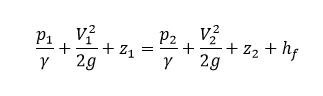
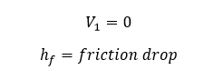
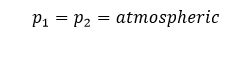
Now, my understanding is that this is free flow out of the tank outlet as if it were open to the atmosphere. But lets say I have the equivalent of 50' of straight 2.5" pipe draining into a sump tank that is another meter below the drain outlet. How does the height difference between outlet and sump tank and the pipe friction between the tanks get included in the calculations? Is it as easy as adding the 1m height difference and subtract the head loss from the pipe to the H value? Does it need to be 2 different calculations?

Thanks.
 
Replies continue below

Recommended for you

Please add a drawing as it makes it easier to understand what you're going on about.

You need two calcs to see if the 2.5" pipe(OD by the look of it) is applying a back pressure or not or is running full or not.

Only then can you decide if in fact the flow is governed by the tank emptying calculation or the pipe friction calculation with 2m head at the start point plus the static head difference (1m)?

Remember - More details = better answers
Also: If you get a response it's polite to respond to it.
 
Ok this is getting more complex.

What are the distance of the horizontal bit and the vertical bit?

You know what the tank can provide so use that flow rate / velocity to do the numbers.

You can look it up up on this site, but I'm pretty sure that if the Froude number of the vertical section is less than 0.3 then the vertical bit of the pipe is free flowing and air will get in from the bottom.

This post in another forum seems to be more or less the same as yours.
Also this one
so then is the head loss in the horizontal bit enough to require a full pipe at the start point (i.e. 2" of water). Now you really need to use open channel flow and as you're at a potential interface between full and open channel flow it does get a little complex, but see how it goes. There was a post here a few weeks ago about flow in horizontal pipes emptying into a pond.


Remember - More details = better answers
Also: If you get a response it's polite to respond to it.
 
Also is this a real question or a theory question?

If you really want it to drain then you probably need a bigger pipe. at >3m/sec coming out of the pipe I just can't see this being a partially full pipe in which case the pipe will start to determine the flowrate rather than the nozzle on the tank.


Remember - More details = better answers
Also: If you get a response it's polite to respond to it.
 
LittleInch,

It's a real question, and unfortunately I can't wait until it's all installed to measure how fast it drains [upsidedown]

You gave me some good leads and maybe over the holiday's I'll be able to investigate and see if I could figure this out, but for now my only option is over sizing pumps and having them cycle. Just don't have the time to go through everything. Plus it likely won't be installed exactly as spec'd so it will be inevitably different from any calcs I do anyways.

Thanks for the input, I'll update if I get it figured out.
 
What's the horizontal distance of the pipe?

Looks to be >10m?


Remember - More details = better answers
Also: If you get a response it's polite to respond to it.
 
Yes, it comes out of the tank and ties in to other drain lines but the actual horizontal distance is ~10'. Equivalent length is probably closer to 50' with the elbows and tees.
 
Free calculator to determine flow out of tank:

Link

With 3 meters of head, this calculator computes an estimated maximum flow of 196 gpm.

Flow will then be reduced by the restriction of the pipe.

Another free calculator to determine fluid flow through a pipe:

Link

With 3 meters of headloss, 50 equivalent feet of pipe, the estimated maximum flow through a 2.5-Inch steel pipe is 170 gpm.

In any case, the maximum flow will only occur for a short time and can be reduced with a catch basin.
 
The difficult aspect of this calculation is to determine the pressure drop or driving force available. You clearly have 2m inside the tank, but can the 1m external vertical downleg be added to that?

If the downleg is submerged in another tank or pond then you can only add the head from the horizontal section of the pipe to the surface of the fluid into which it is discharging. If the discharge is submerged you can assume that eventually all the air in the pipe will be flushed out and the pipe will run full of liquid and you can take the height difference as credit towards the driving force.

If the discharge is not submerged then for the head gained in the downleg to be used as driving force we must be sure the downleg will run full. If we assume the full height difference of 3m is available then the flow rate will be around 170 USgpm with a velocity of 11.4 ft/s and a Froude number of 4.3. It is a fairly safe bet that the pipe will run full like this.

This raises the interesting question - can the flow rate be increased by making the downleg longer? Theoretically, if you could add another 2 m of vertical downleg you could increase the flow rate to about 200 USgpm.

Katmar Software - AioFlo Pipe Hydraulics

"An undefined problem has an infinite number of solutions"
 
I prefer to have a basic approach:

Consider points 1 at tank liquid surface and and 2 at drain outlet.
image_jgnjf8.png


Using Bernoulli equation

image_wbmuqk.png

image_mpakdx.png

image_xn2b9j.png

image_xconxh.png


Since the flow is non-steady, at the particular moment, the velocity V_2 can be solved by using friction flow formula.

Regarding part filling of pipe, it will happen only when flow is very low and hence should not be very important.

The contraction of flow at tank outlet will be considered in friction drop calculations using appropriate formula.
 
Ggrififn,

We know nothing about your system so the pump sizing makes no sense and also if the level changes in the tank then it all changes.

But bimr and katmar appear to have given you the results (basically 170-200 gpm) and the fact that the velocity and Froude number are so high means that the pipe will be full and the fluid (water?) will be pouring out like a fire hose!

You have clearly simplified the piping arrangement for us as you only show one elbow, but if you want more flow then try and simplify the piping layout or put in a bigger pipe!

Remember - More details = better answers
Also: If you get a response it's polite to respond to it.
 
With equivalent length of 50 ft, using basic formula above, and h_f=f *L/D *V^2/2g, the flow will be close to 157.6 USGPM and velocity is 3.29 m/s (10.8 ft/s). So it agrees well with earlier calculated values. Sorry for goof up (in unit conversion) earlier .
 
Status
Not open for further replies.
Back
Top