Eng-Tips is the largest engineering community on the Internet

Intelligent Work Forums for Engineering Professionals

  • Congratulations waross on being selected by the Tek-Tips community for having the most helpful posts in the forums last week. Way to Go!

Tank overflow

Status
Not open for further replies.

bootlegend

Structural
Mar 1, 2005
289
0
16
US
It's been years since I had my physics and fluids classes but I finally need them now. Problem is I've apparently forgotten the little I learned.

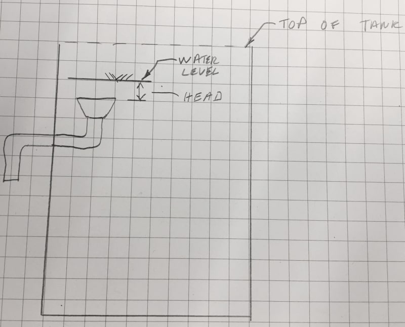
I have tank that can have water overflow at a given rate. Tank is open to air pressure at overflow location. I need to size a pipe to handle the overflow rate and prevent spilling over the edges of the tank. If the pipe is large, then pressure doesn't buildup, but if the pipe is smaller pressure can build up. Is the Bernouilli equation all I need to solve this? I found this chart online and I think that addresses the situation for a roof drain, but how are they building the chart?


Replies continue below

Recommended for you

thats not going to cut it
your sketch will not work very well as it does not allow for much head to build and overcome the entrance loss or pipe friction loss unless you can put a sufficiently large pipe in to handle the overflow without flowing full.

generally, a tank overflow looks more like this:

IMG_3858_ruu2o3.jpg
 
cvg,
Thanks for the reply. My sketch was meant to be conceptual but I see that it wasn't clear. I do see what you mean about needing a pressure head to overcome the orifice friction loss. What I actually have is two overflow pipes coming out of two sand classifying tanks. The manufacturer has the overflow stubbed out as a pipe with a flange. What I'm trying to do is collect two of these overflow outlets into one drain pipe. I have the pipe height and slope. I think the spreadsheet GeoEnvGuy linked to has some info that will help me out.

 
That's the one to use. You're in open channel flow with a drain line at an angle.

The previous link isn't clear what percent filled, but looks like 100%

I wouldn't go more than 30-40% full.
Pretty sure you don't want to have a froude number more than 1.

If your pipe ever goes vertical then you're in a different place as well.

Remember - More details = better answers
Also: If you get a response it's polite to respond to it.
 
also make sure you include a minor loss at the junction of the two drain lines and include sufficient safety factor to handle entrained air.
 
This thread might also prove useful
If not it's a good read anyway.

Bottom line you can either have a small pipe wich is 100% full but you then need to control the pressure at the base to create a permanantly full pipe which then releases flow to maintain a fixed liquid height / backpressure. Too complex usually.

Or have a much bigger pipe but with care that the flow doesn't become unstable or start to go two phase.

For vertical pipes there seems to be a magic number of 7/24 full and a velocity of 10-15 feet per sec. This allows air to travel up the pipe and can continue in steady state for hundreds of feet vertically.

Put it on a slope and it becomes an open channel and size increases again as you don't want to get into unstable flow ( I think this is the Froude number going>1, but I'm not 100% about that.

You can envisage a flow happily going along a gentle slope smoothly and then as you add more and more flow or slope angle it starts to "jostle" with each other and become unstable.


Remember - More details = better answers
Also: If you get a response it's polite to respond to it.
 
Thank you all for the input. I read through the referenced threads and it appears this isn't a completely straightforward problem. I took another stab at the problem using the Manning equation, assuming the pipe is half full. If I understand correctly I have plenty of extra capacity even at half full so I think the losses from a couple should be okay. Also, I'm allowing for the total input into the tanks which only some portion should ever come over the end weir to discharge. Majority should be pulled out at other locations along the length of the tank.

 
 https://files.engineering.com/getfile.aspx?folder=f9007d7d-17c7-46a5-bd3f-1ec93f56318c&file=tank_2.pdf
I think you would be best to have your two short lines from each tank either slope down into the hopper / junction box or discharge high into it to avoid any interaction between the two flows.

Then have your long sloped pipe.

Remember - More details = better answers
Also: If you get a response it's polite to respond to it.
 
Status
Not open for further replies.
Back
Top