Continue to Site

Eng-Tips is the largest engineering community on the Internet

Intelligent Work Forums for Engineering Professionals

  • Congratulations IDS on being selected by the Eng-Tips community for having the most helpful posts in the forums last week. Way to Go!

Taper detail for hemispherical head to shell welding

Status
Not open for further replies.

Paulettaa

Mechanical
Mar 17, 2018
60
Dear all

I wonder if I have fully understood the taper design as per ASME BPVC VIII.
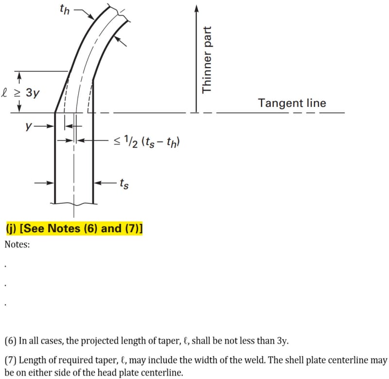
in VIII-1 it says the length of the taper shall not be less than 3 times the thickness offset.
then it says the length of the taper may include the width of the weld.
weld_VIII-1_gpmycx.jpg


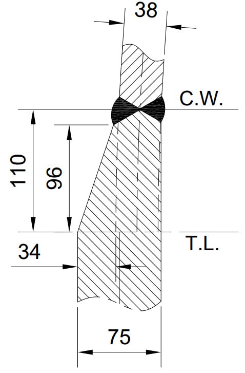
I wonder if the weld taper detail in the following figure meets the requirements of the code (all dimensions in mm):
2018-09-15_7-47-48_elysfv.jpg


On the one hand 96 is less than 3*34. on the other hand 110 is more than 3*34. the note (7) says length of taper may include the width of the weld.
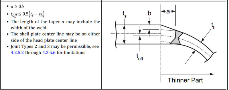
Division 2 part 4 also gives the same detail as per table 4.2.5
weld_VIII-2_lx2aym.jpg


So is the detail correct or not?
 
Replies continue below

Recommended for you

Look again at the detail: The 110 mm dim is to the "exact" projected "middle" of the larger weld. it is to nominal weld prep center point.

The 96 dimension is to edge of the weld prep.

Look at distance "a" - it is also extrapolated to the nominal weld prep center point of the weld, which is on a curved head - so the inside and outside weld "edges" are not symmetrical. The "a" dimension on a curved surface appears close to the edge of the outside weld prep, to the near-center of the inside weld prep, but it is defining a different point unique to this curved PV head.

 
Good engineering practice: 1) try to be coincident centerlines of plates to be butt welded , 2) avoid abrupt changes and ground flush this weld.

Regards
r6155
 
r6155:

Good point. The intent is to have a very smooth, well-blended surface from Ts to Th.
Length of the (to the weld prep in the middle of the taper) should be at least 3x the offset from large wall to small wall.

In the second illustration, a hemispherical head of thickness Th could NOT be fillet welded to the shell of wall thickness Ts.
 
The first and the third figures are not my design, they are ASME VIII-1 and VIII-2 respectively and are valid. What I want to know is whether the second figure is acceptable or not as per these two approved designs by ASME. The code clearly says the taper length may include the weld width. So can I consider the length of the taper to be 100 mm.

One more thing about the second illustration is that the dimensions are real but the weld is schematic and it will be ground at the final stage.

Warm regards
 
Paulettaa
1)Never mix real with schematic detail drawings. Never !!
2)What is the meaning of C.W.?

racookpe1978
3)fillet welded?,....where?

Regards
r6155

 
Thank you r6155.
This drawing is not a shop drawing. I just made it to ask my doubts regarding the length of the taper and you are right that it is not a good practice to mix real and schematic.
C.W. stands for circumferential weld.
 
Paulettaa
The weld in your drawing is longitudinal. All welds in sphere are category A. See figure UW-3.

Regards
r6155
 
"Fillet weld" was used as an example of how NOT to create a taper when two PV wall thicknesses are connected.
 
r6155
the weld in my drawing is definitely a circumferential weld. The fact that this is a category A weld does not make it a longitudinal weld.

ASME BPVC VIII-1 UW-3 (a) said:
(a) Category A. Longitudinal and spiral welded joints within the main shell, communicating chambers, transitions in diameter, or nozzles; any welded joint within a sphere, within a formed or flat head, or within the side plates of a flat‐sided vessel; any butt-welded joint within a flat tubesheet; [highlight #EF2929]circumferential welded joints[/highlight] connecting hemispherical heads to main shells, to transitions in diameters, to nozzles, or to communicating chambers.

Anyway, do you think the taper is acceptable by the code division 1 or 2?

Warm Regards
 
Yes, to me your detail is acceptable in both Div.1 and 2. It would even be acceptable with 90 in place of quote 110 (38 being the minimum head thickness after forming). You didn't clearly describe your doubts: why shouldn't your detail be acceptable?

prex
[URL unfurl="true"]http://www.xcalcs.com[/url] : Online engineering calculations
[URL unfurl="true"]https://www.megamag.it[/url] : Magnetic brakes and launchers for fun rides
[URL unfurl="true"]https://www.levitans.com[/url] : Air bearing pads
 
Agree, your detail looks acceptable. We have performed hemi-head to shell welds in the same way.

Just a couple of details to be careful about:
[ol 1]
[li]Make sure that your hemi head is purchased with a slightly larger ID than your vessel ID to account for the slight trimming that will be required.[/li]
[li]Make sure that your shop actually trims the hemi head. You need to make a note somewhere on your drawing indicating that trimming is required.[/li]
[/ol]

Cheers,
 
Paulettaa
From TL the transition thickness is part of the hemispherical head, not a cylindrical shell. Hence all welds in head are longitudinal. Radius of head is in the TL.
UW-3 (a) Category A. Longitudinal and spiral welded joints
within the main shell, communicating chambers,66 transitions
in diameter, or nozzles; any welded joint within a
sphere, within a formed or flat head.


If hemispherical head has the same thickness of cylindrical shell and the welding joint is in the TL this weld is circumferential

UW-3 (a)………….;circumferential welded joints connecting
hemispherical heads to main shells

UW-3 (b) Category B.……….. circumferential
welded joints connecting formed heads
other than hemispherical to main shells, ……….

More information see BS EN 13445-3

Your design complies with ASME VIII , but I prefer coincident centerlines of plates.
More NDE is required with your design.

Regards
r6155
 
r6155
I believe you are interpreting UW-3 incorrectly. Read the first sentence of UW-3.

The term “Category” as used herein defines the location
of a joint in a vessel, but not the type of joint.

UW-3(a)Category A. Lists Welds that are Category A joints. Longitudinal welds and spiral welds within the main shell.... and any welded joint within a sphere are Category A joints. Just because a joint is in a sphere does not make it a longitudinal joint. It makes it a welded joint within a sphere ergo a Category A joint.
 
Don56
The following are some clarification:

BS EN 13445-3:2009 5.6 Joint coefficient
For the calculation of the required thickness of certain welded components (e.g. cylinders, cones and spheres), the
design formulae contain z , which is the joint coefficient of the governing welded joint(s) of the component.
Examples of governing welded joints are:
⎯ longitudinal or helical welds in a cylindrical shell;
⎯ longitudinal welds in a conical shell;
⎯ any main weld in a spherical shell/head;
⎯ main welds in a dished head fabricated from two or more plates.

The following welded joints are not governing welded joints:
⎯ circumferential weld between a cylindrical or conical shell and a cylinder, cone, flange or end other than
hemispherical;
⎯ welds attaching nozzles to shells;
⎯ welds subjected exclusively to compressive stress


5.7.2 Longitudinal joints
The components of cylindrical or conical shells, spherical components, and domed or flat ends shall be assembled
by butt welding, using a welding procedure that ensures full penetration.
The mean lines of the components that form longitudinal joints of cylindrical or conical shells as well as joints on
spherical shells shall be aligned in the vicinity of the welded joint within the manufacturing tolerance limits given in
EN 13445-4:2009. Bending effects shall be taken into account in the design.

5.7.3 Circumferential joints
The mean lines of components of same thickness shall be aligned within the tolerance limits of EN 13445-4:2009.
The mean lines of components of different thicknesses may be non-aligned, but the offset shall not exceed the
alignment of inner or outer surfaces within the tolerances limits given in EN 13445-4:2009.

------------------------------------------------------------------------------------------------------------------
ASME BPVC.III.1.NB-2017
Joints in spherical vessels, joints within heads, and
joints between cylindrical shells and hemispherical heads
shall meet the requirements in Table NB-4232-1 for longitudinal
joints.

Regards
r6155


I also do not see how this would be a longitudinal joint....the references quoted are not from Sec.VIII Div. 1
As Pauletta pointed out "circumferential welded joints connecting hemispherical heads to main shells" are Cat. A
 
david339933
You not need to "see" how this would be a longitudinal joint, you must "CONSIDER" as longitudinal joint.
No matter the shape of the butt welds are in the sphere, if it is meridional, latitudinal, zig-zag, parallel, girth, etc. All butt welds are "CONSIDERED" longitudinal in the sphere.
For a hemispherical head the axial and meridional stresses are identical

Weld line is part of the hemispherical head, hence is "CONSIDERED" longitudinal weld cat A.

The wall of a pressurized spherical vessel is subjected to uniform tensile stresses in all directions

The transition is part of the stronger head, the shell is not tapered down on the straight section because it needs the full thickness

Inspections of longitudinal butt welds are not the same as circumferential butt welds.

ASME I- Power Boilers
PG-26 WELD JOINT STRENGTH REDUCTION FACTOR
At elevated temperatures, the long-term strength of
weld joints can be lower than the long term strength of
the base material . Table PG-26 specifies a weld joint
strength reduction factor, w, to be used to account for this
lower long-term strength in determining the required
thickness of components operating in the creep range.
This factor shall be applied in the design of cylinders containing
longitudinal butt welds and to hemispherical
heads or any other spherical sections that comprise segments
joined by welding.

PG-29.11
Joints in full-hemispherical heads including the joint to
the shell shall be governed by and meet all the requirements
for longitudinal joints in cylindrical shells, except
that in a buttwelded joint attaching a head to a shell the
middle l ines of the plate thicknesses need not be in
alignment.

Please, try to read the books.

Regards
r6155

 
Hasn't this hair been sufficiently split by now?

Regards,

Mike

The problem with sloppy work is that the supply FAR EXCEEDS the demand
 
Status
Not open for further replies.

Part and Inventory Search

Sponsor