Continue to Site

Eng-Tips is the largest engineering community on the Internet

Intelligent Work Forums for Engineering Professionals

  • Congratulations KootK on being selected by the Eng-Tips community for having the most helpful posts in the forums last week. Way to Go!

Tapping into Power from Wall Outlet Receptacle? 1

Status
Not open for further replies.

metalman8357

Materials
Oct 5, 2012
155
Hello All,

I am working on a product that will be an actively powered face plate for a wall outlet receptacle. Basically the socket will provide power for my faceplate and I need to tap into the power of the outlet. There is a company that makes an active face plate (
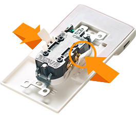
breakdown_charger_1_pvmi1d.jpg
) and they use a patented clip out of the back of the faceplate to make contact with the terminal screws on the outlet to provide power. I would love to use this mechanism to power my face plate but unfortunately the mechanism is patented!

The simplest method would be to just use two wires out of the back of the face plate and have an open ring terminal on the end of the wires that could be used to slip under the existing screw terminal that holds the mains power lines (
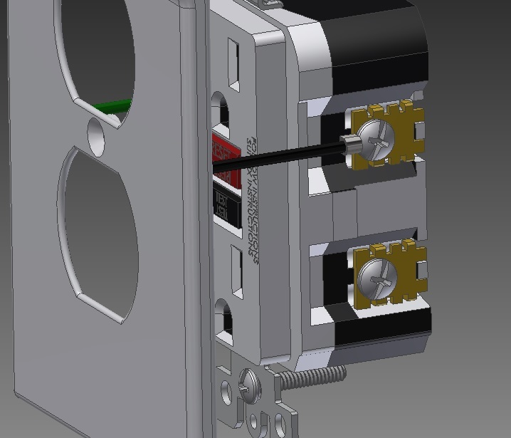
Connection_to_Terminal_dzzkgm.jpg
). Unfortunately I've been told that this configuration would violate the electrical code which prohibits two wires being used on the same screw terminal?

I am not well versed on the code but basically I need a way to attach my Hot and Neutral wires from my actively powered faceplate into the existing wall socket without infringing on the patent as discussed previously. Is there a simple solution I'm just not seeing?

Any input would be helpful!
 
Replies continue below

Recommended for you

The binocular faceplate is not going to fit on a Decora socket.

Ring terminals won't work because the terminal screws usually have deformed points and cannot be fully removed.

Have you negotiated with the patent holder?

You can read the actual patent claims to see if there is another way to get there.


Mike Halloran
Pembroke Pines, FL, USA
 
So, who the he!! even wants a powered face plate? I know the risks and I sure as heck don't want 120V into the face plate that supposed to separate me from the live parts. What the heck could justify that kind of nonsense? Power where power belongs, and no where else.
 
A forked terminal instead of a ring terminal?
It may not be compatible with all receptacles.

Bill
--------------------
"Why not the best?"
Jimmy Carter
 
To clarify I would want to be using a forked terminal not a ring terminal so that it can slide under the existing screw terminal that holds the live and neutral wires.

Does this configuration violate code? I am not interested in hearing about the usefulness of the product just whether or not my proposed design will be code compliant.

Thanks again for the input!
 
Hi MM,
You have not indicated what this 'active' face-plate will be powering.

If this is a new product that you intend to sell en masse, what about the required UL (or CSA) approvals?

I doubt that you will be permitted to tap off of the receptacle terminals, as you have indicated above. It may be possible to tap off of the upstream wire-nuts (located in the box). However, the application to UL (or CSA) may permit either. It really does comes down to what UL (or CSA) will permit. A better approach might be to provide the receptacle as an integral part of your device; that way the approval would be for an entire assembly, which might be easier to obtain.
GG

I am forever learning and changing.
W.E. Deming
 
I do not think it is permissible to put your forked terminal under the same screw that is terminating a wire. You could use the other screw, unless the bridging link has been removed. Then you face the problem of securing the receptacle with faceplate attached and occluding the mounting screws.

Mike Halloran
Pembroke Pines, FL, USA
 
Thanks Groovy Guy for the response. I'm really trying to avoid having to provide the actual wall receptacle because this increases complexity. My product will be an active face plate with a step down transformer and will therefore require UL approval on it's own.

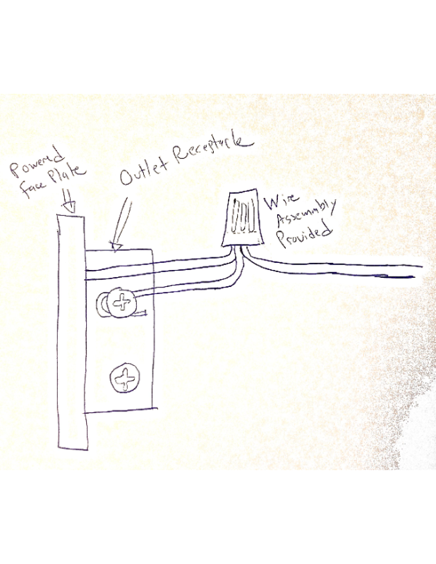
What if I used the setup shown in this sketch here (
Outlet_Receptacle_Sketch_s6g53t.png
).

Basically I would provide my active face plate, and then provide a three wire configuration as shown in the image. All the user would have to do is clamp one end of the pigtail to the outlet receptacle screw and the other would be connected to the power line with a wire nut provided.

Would something like this need UL approval? Is the UL pretty open about answer questions like this so that I can clear this up before proceeding with the rest of my designs?
 
It should not take an electrician to install a faceplate. Homeowners and painters should be able to remove and install them without risk. I find the patented device to also be troublesome. It may be reinstalled upside down putting it on the source side of a GFCI for example rather than the load side. Why not simply use the receptacle to make the connection? I've had listed GFCIs and splitters that simply plug into a duplex receptacle, either covering or replacing the faceplate.
 
The reason that I do not want to have to use the receptacle for the connection is because I want to keep it very minimal and slim. By blocking off the receptacle, the product would be very thick.
 
The active portion of the face plate is part of my invention that I'm currently filing a provisional patent on. I can disclose more later. For now I just need a good way to tap into to power without violating any code requirements.
 
Hi MM,
I don't foresee any leeway on the UL/CSA issue; it will be required, especially since the internals will be powered at 120Vac. I checked a couple of blank (ie dumb) face plates in my shop; even they are UL/CSA approved.
Sorry.
GG

I am forever learning and changing.
W.E. Deming
 
Hi GroovyGuy,

I think you misunderstood. I am absolutely going to seek UL/CSA approval for my active face plate product. It will be inputing 120VAC and outputting 5VDC and will therefore we classified as a power adapter.

What I don't want to do is have to provide the actual outlet receptacle itself because then I will need UL approval for this portion as well. I want my customers to be able to use their existing outlet receptacle and just wire in my active face plate (that is UL approved and has the electronics incorporated into it). If you could take a look at the sketch I uploaded above and let me know if this wiring configuration would be code compliant?

Thanks again for all the help guys!
 
Hi MM,
I think that your sketch will be doable. I don't think you'll have any issues in obtaining UL/CSA approval with that approach.
Good luck,
GG

I am forever learning and changing.
W.E. Deming
 
Does this look a bit difficult to wire to anyone else?

USB charger perhaps? Since the electrician needs to remove the receptacle to make up the connections anyway, not much is gained by retaining the existing receptacle. Just replace the receptacle with a combination device and reinstall the old cover.
 
Given the number of different receptacle termination screw configurations, I doubt that you will be able to find a "One Solution Fits All" answer. The patented device looks like it is quite universal, but with that solution spoken for you may have difficulty coming up with an acceptable similar solution. Check the patent for loop-holes.
By the way, I haven't seen a receptacle where the wires wind around the screw for quite some time. Most devices have a pressure pad under the screw head and the wire is inserted below the pressure pad. with some you could use a forked terminal between the screw head and the pressure pad but on other receptacles the pressure pad is captive and the screw head may not be able to separate from the pressure pad enough to insert a forked terminal.
Serious reconsider supplying a compatible receptacle with your faceplate. The receptacle and the faceplate may be packaged together but not assembled together to avoid added certification of the receptacle.

Bill
--------------------
"Why not the best?"
Jimmy Carter
 
Just because they have a patent in that system, doesn't meant it passed UL listing. I seriously doubt it did.


"You measure the size of the accomplishment by the obstacles you had to overcome to reach your goals" -- Booker T. Washington
 
stevenal, it looks quite awkward to connect and to retrofit.

Are there really captive screw terminals on the side of the receptacle as shown in the images? That to me just looks like asking for trouble when someone manages to stick their fingers in to remove the receptacle. All the receptacles here have shrouded terminals on the rear of the plate, rather than the sides.

I'd be aiming for a replacement receptacle as well, its just about guaranteed that there will be some receptacles that won't fit the faceplate properly, necessitating replacement.
 
I actually would expect you could get a UL listing on wire tails to put behind the screws, even with a wire already on the screw. I could see 2 ways to do it. Either put it behind the screw head by making it quite heavy so the screw doesn't deform it or make it so it fits to the receptacle first with the wire on top of it.

These days, many electricians stab the wires into the quick connect holes instead of attaching them to the screws anyways.

Now, personally I can see the lure of the Snap Power products because they can be installed and removed without having wires. But, the chances I would install a hard wired cover plate charger or night light are very slim. If I have to shut-off the power and pull-out the receptacle then I would just swap the receptacle for a combination USB charger device. As for a night light - I'd probably use a plug-in light instead of a hard wired cover plate. These cost about the same as the Snap Power products after-all. You will find that MANY homeowners won't want to install a hard wired solution because it requires actually working with electricity. But maybe you have some amazingly cool new product that would be so desired people will pay an electrician $100/hr to install it?

The back side of the Snap Power charger is very deep, as in the receptacle has to be sticking out of the wall and box a fair bit for the front of the cover to actually be flush with the front of the receptacle. From my experience installing 100's if not 1000's of receptacles and cover plates, the Snap Power plate simply won't work worth a crap. The only way I could see it install correctly is by spacing the receptacle from the wall and box with spacers behind it's mounting ears. So, make sure your product is almost flat on the back side like most normal cover plates so it will install nicely.

 
Status
Not open for further replies.

Part and Inventory Search

Sponsor