Eng-Tips is the largest engineering community on the Internet

Intelligent Work Forums for Engineering Professionals

Target flow rate for a full pipeline 2

Status
Not open for further replies.

Muud

Materials
Nov 29, 2017
44
0
0
NL
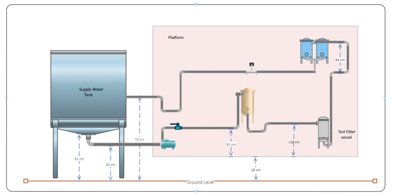
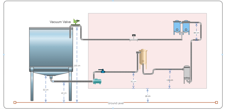
I want to modify an existing filter test setup with a 2 inch piping. The usual flow rates are 10 m3/hr and higher. To be able to test a different type of filter for which flow rates are quite low 1 -3 m3/hr on the same system I doubt that the pipes will remain full. The test fluid is water. Is there a way to calc. what is the minimum flow rate for the existing pipes to keep them full at all times?

 
Replies continue below

Recommended for you

Yes there is, but a lot then depends on the slope and how the pipe empties to atmosphere.

You could simply install an upside down U bend with the top higher than your filter to maintain a full pipe.

Only if your downstream pipe is sloping continuously to an open end will the water run out faster than it comes in and hence get open channel flow.

It's not a big issue though so not sure why you're concerned?
A decent sketch and profile would be useful to see if you've got an issue or not.

Remember - More details = better answers
Also: If you get a response it's polite to respond to it.
 
The pipe empties the water back into the main tank (open) so forming a closed loop.

If there is a partially full flow then it will be an issue for the electromagnetic flow measurement, inline sampling as well as for other sensors.

I am preparing a sketch and will upload it here. It will give you a much clearer idea of the existing setup.
 
Put a plug valve on the end just before entering the tank. You can adjust the valve and outlet flow to ensure your pipe remains full going through the filter.

 
If the pipe empties above the water line in the tank then it's an open loop. A closed loop would be if it entered the tank under the water level.

A simple high point with a vacuum breaker will create and maintain a full pipe at any flow including zero. A valve will only help if you have sufficient flow to blow all the bubbles out.

Remember - More details = better answers
Also: If you get a response it's polite to respond to it.
 
I have drawn the sketch and hopefully it gives you a clear idea of the layout.

EE-_Layout_dplu6g.png


The pipe elevations shown on the platform are measured w.r.t. the platform and thus those without any height are not elevated.

Is a vacuum breaker valve same as an air release valve?
 
Ok, To make your system always full then simply make your last set of connections past the meter to include an inverted U bend, with the pipe higher than 110cm off the platform and insert a vacuum breaker on the high point. The route the down pipe in a continuous slope or flat into your tank ABOVE the water line in the tank.

A vacuum breaker lets air in, an air release valve lets air out. Sometimes they can be the same thing, sometimes not. always check.

Remember - More details = better answers
Also: If you get a response it's polite to respond to it.
 

Ok. Thanks for your advice.

I have never worked with vacuum breaker valves so your statement "it lets air in" seems opposite of what we want.

I will search these kind of valves :)
 
Well this is only for the last bit of piping as it drains into the tank.

But the high point downstream of the meter will mean that regardless of your flow rate, the pipes will always be full of liquid so long as you either vent the filters etc or flow at a high enough velocity initially to blow out all the air bubbles.

You want to drain above the water level so that you don't get any air locks or two phase flow going on. Much simpler to just empty above the water line.

on the other hand, if your current set up is below the water line then you may not have a problem providing that you can eliminate the air once you've changed equipment.

At its simplest a vacuum valve is just a bit of pipe open to atmosphere sticking vertically up for say 1m as the pressure drop in your last bit of pipe will be very low.

Remember - More details = better answers
Also: If you get a response it's polite to respond to it.
 
To incorporate both a u-bend and discharge of the return path, I am thinking of combining the two. Something like the following:

Existing_Layout_EE_with_vacuum_valve_u_bend_j06fff.png


I suppose if the pump can cope with the increased discharge head, we can implement the setup without creating other problems. Do you see other potential issues?
 
Looks good to me.

If you want to ensure a full pipe at all times then something needs to change and this looks like a simple piping change to me.

When you change the test element there will be a little bit more water to drain out but pretty small.

Remember - More details = better answers
Also: If you get a response it's polite to respond to it.
 
Just stops the system syphoning down. Maybe not needed but they are simple and cheap.

Remember - More details = better answers
Also: If you get a response it's polite to respond to it.
 
I will wait for Katmar to suggest drilling a hole in the top of the gooseneck, or cutting off the last bit of downleg entirely and discharging over the tank rim.

 
what ever.

So long as the highest point on the system is at the top of that pipework, it matters not.

Remember - More details = better answers
Also: If you get a response it's polite to respond to it.
 
Status
Not open for further replies.
Back
Top