Eng-Tips is the largest engineering community on the Internet

Intelligent Work Forums for Engineering Professionals

  • Congratulations waross on being selected by the Eng-Tips community for having the most helpful posts in the forums last week. Way to Go!

Teamcenter Visualization 9.1 - Create Coordinate System 1

Status
Not open for further replies.

CAD2015

Computer
Jan 21, 2006
1,926
US
Good morning,

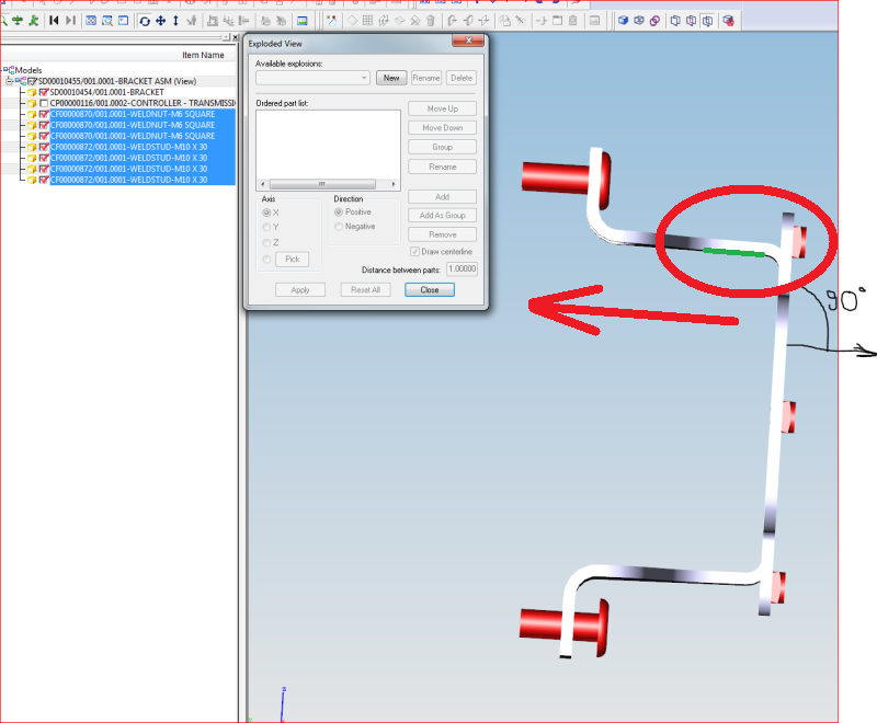
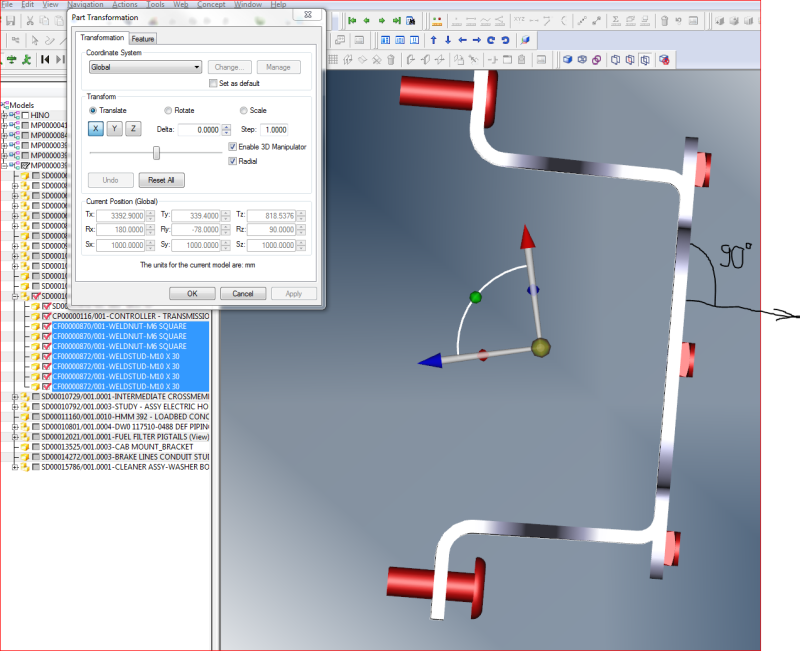
I need to move (Part Transformation) the highlighted components using a coordinate system. If I use "Enable 3D Manipulator" the direction of movement would follow the current coordinate system (X=0, Y=0, Z=O), which is not aligned with the components (the blue arrow is not perpendicular on the axial direction of the components).
How could I move the components on the direction of the black arrow (perpendicular on the gray bracket)?
How could I create a coordinate system perpendicular on the gray bracket?


blob_zuazmb.png


CAD 2015
 
Replies continue below

Recommended for you

I am currently running TC8.3, but, if this is anything like the "Dynamic CSYS" in NX, you should be able to align this "3D Manipulator" to your part by selecting the red arrow then selecting a vertical edge you want to align it with. Then, click and drag the blue arrow to move your components. Visualization may be a different animal entirely, but that would be my first approach.
g.

gbangs
TC 8.3.3
NX 8.5.3.3 MP11
 
Thanks, Gbangs,

Another question: How could I get the same result by using the Exploded View?

blob_eopdye.png


CAD 2015
 
I'm suggesting blindly here not running 9.1, but you may need to orient the 3D Manipulator to the desired position then Save it (if it allows). In exploded view mode you might have to Pick the one you saved instead of "X" "Y" or "Z". Or "Pick" might give you some options to define the axis?

gbangs
TC 8.3.3
NX 8.5.3.3 MP11
 
Thanks again......

The "Pick" option is still a dilemma for me......
I do not know how to use it.
How is it in TC8.3?........

CAD 2015
 
VisView 9.1 looks more like TC 8.3 Structure Manager, but we don't have an easy way to create exploded views (it can but, I've never used)(Note to self; upgrade to 9.1 or better asap [wink]). "Pick", I assume, would be to define the directional vector by choosing from various methods; edge, cyl axis, normal to face, etc... which could be different from defined csys. It also helps in that you don't have to save multiple csys's all over the place, just define the direction as you need to from existing geometry.
Does the software offer a list of methods when you click on "Pick"? If not, it may just be waiting for user to give an input by selecting an entity to define the vector.
In your example, selecting the edge/line (assumed) in green would produce a vector in that direction as shown by red arrow. It probably can't be an arc, but a line, any straight edge will do will to define a vector going in that same direction. You have the option to then select "Positive" or "Negative" direction if you want to flip it. That's what I see from the menu shown.

Good for now?

blob_eopdye_ncwdur.png


gbangs
TC 8.3.3
NX 8.5.3.3 MP11
 
Gbangs,

I have no idea why, but I can't select any vector form the geometry that I have .
I might be wrong with something, but I do not know where......

CAD 2015
 
Well, I suspect that bracket is made with a lot of curves and bends, hardly a straight line in there? In NX, there are multiple ways to select/define a vector, it's just a matter of what they've allowed for in VisView.

From the Help files:

"5.In the Axis section, select the axis along which you want the parts to explode.

-or-

In the Axis section, click Pick, and then use the 3D Selection toolbar to pick a part surface or edge.


6.In the Direction section, select a direction for the parts to explode along the specified axis. "


g.

gbangs
TC 8.3.3
NX 8.5.3.3 MP11
 
Great reply, thanks a lot Gbangs!

blob_v8gx1i.png


CAD 2015
 
Status
Not open for further replies.

Part and Inventory Search

Sponsor

Back
Top