Eng-Tips is the largest engineering community on the Internet

Intelligent Work Forums for Engineering Professionals

Temporarily Reinforcing Existing CMU Wall

Status
Not open for further replies.

AndBre44

Structural
Sep 13, 2019
17
0
0
US
Hello all, I'm hoping someone here can look at my methodology of reinforcing an existing CMU wall for a new building construction. The plan is to demolish the East, West, and South walls but maintain the North most wall for the new building construction, as well as the slab of the original building. For conservativeness, I'm attempting to design for this CMU wall to act as a cantilever out of the ground and apply wind load against the face of it at a uniform 20psf, however with the wall being at 14' tall the loads applied seem to be a bit too much to just be resisted with some sand bags on the bottom sole plates. I've attached a PDF with a quick CAD sketch of the condition as well as the original temporary shoring idea I had.

CMU_Wall_Plan_kfssmq.jpg


CMU_Wall_Section_ss5pba.jpg


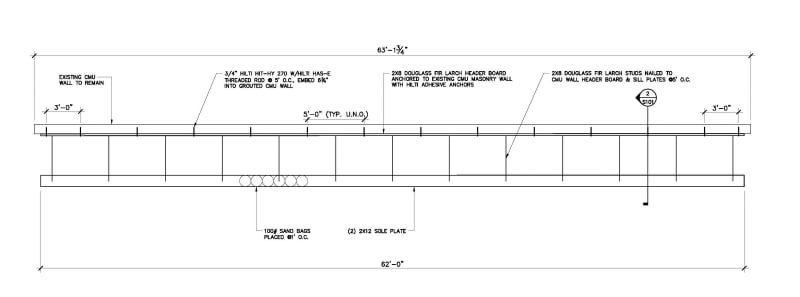
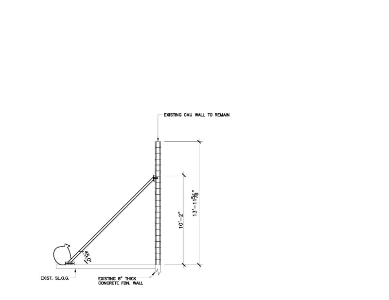
The main concern I'm having is figuring out a proper way to secure the bottom sole plates in a way that they can handle the potential resulting load - approximately 280lb/ft in the x and y directions - seeing that all I have below is a 5" thick slab that I would like to avoid having to place a multitude of anchors into if I can help it. Any thoughts or insight into the matter would be greatly appreciated.

As an EIT, I'm open to being wrong now if it means being right when it counts.
 
Replies continue below

Recommended for you

I love that you are opening yourself up like this. Hopefully you will learn more quickly.

Some criticsm of what's shown on the sketches above:
1) Douglas Fir-Larch is a little "high-end". #2 Southern Yellow Pine is probably more readily available and cheaper for the small qty you'll be using.
2) Design for a maximum wood member length of ~16ft. Again, price and availability - and ease of handling in the field. This might affect how often and where the shores are located for your header / wale.
3) I would guess that the Contractor will want to use metal pipe shores or bracing. Provide the minimum dimensions and design forces and let the Contractor figure what shores to use.
4) Dimension the shore spacing on your bid plans. It looks like 5ft C-C.
5) Do the math on the anchor design for your shore spacing. 0.28k/lf x 5lf = 1.4k/anchor in shear. Evaluate if this is possible to get out of the slab using a commercial post-installed anchor - either adhesive or mechanical. You should have a feasible solution prior to sending it out to bid. If you let the Contractor figure it out you will get change ordered if it doesn't work - this can affect your Errors and Omissions insurance. Indicate whether the anchor needs to be removed. Provide design loads OR specify an anchor that works. I personally specify removeable mechanical anchors if possible as they patch nicer and don't leave steel in places where you might want to put something else in the future.
6) Check if you will need strongbacks vertically to resist flexure between the wale and the slab.
7) My Hilti rep would slap me I'm sure, but check out other anchoring lines. Simpson Strong-Tie has a wide selection, decent software and their anchors can be less expensive.
8) Not sure your wale (you call it a header) is terribly effective in the flat position and with holes in it. Consider piecewise aluminum, steel or wood ledgers (doubled pieces with spacers so you can install stuff thru the middle) / strongbacks horizontally. Again, assume limited length for ease of handling / erection in the field.

I hope that some of this is helpful to you.
 
You don't need to worry the force in Y direction, as it gets down to the ground. For X (shear), the total force is 280*5 = 1400 lb/support. You can design a weight to over come it. For construction, a safety factor 1.5 to 2 should be considered.
 
retired13,
Be careful how you reply here. The Y (vertical) direction load on the bottom of the brace is indeed critical and has nothing to do with the wall weight.
The base of the diagonal brace will see horizontal shear across the slab surface as well as vertical forces(up or down depending on wind direction).


Agree with JAE. The braces will transmit vertical forces at each end (to BOTH the CMU and slab) by virtue of the geometry when resisting horizontal forces.
 
JAE,

Thank, I completely forgot the uplift case. But if he can get shear under control by adding weight, the lift will be much less than the added weight, since the developed shear resistance is through contact friction, a fraction of the weight.

EDIT
Fully agree with jdonville. Metal scaffold system is better, though more expensive.
 
JAE,

Yes, my thoughts exactly as far as the vertical loads depending on the wind direction, and in a worse case I would imagine wind blowing onto the wall in what is right on the section, thereby incurring some vertical pullout. Thank you for confirming.

jdonville,

A lot of what you said was extremely helpful, and I definitely appreciate you taking the time to provide a multitude of comments. The sent images were only meant to be sketches to express the ideas, I mainly wanted to show the dimensions I had to give an idea of my process haha so I'm sorry if my drafting wasn't quite to par. I had done the anchor design at 5' for the CMU and that anchor did pass, but I wasn't entirely sure how I would then correlate that to the wood framing, hence why I tried to use some kind of interface (which I now see would be called a wale board) to properly connect the bracing to the base of my configuration.
The original plan was to attempt to use adhesive anchors throughout this design including the portion on the ground. However the thing that I think is mainly throwing me off is the fact that whatever I do use as an anchor, Hilti or Simpson, would be only going into the existing slab, and I'm attempting to avoid using anything with an embedment depth greater than 3.5" because of this, hence why I at first was thinking of using the sandbags instead. Is that a correct way to be thinking about this? Or is there something I'm missing that maybe would simplify/clarify the process?

As an EIT, I'm open to being wrong now if it means being right when it counts.
 
This is construction bracing, correct? If so, take a look at ASCE 37, Design Loads on Structures During Construction. There are guidelines there for using reduced wind loads based on the idea that the building will only be in that state for a few weeks rather than 50 years (really cuts down on the probability of experiencing a design level hurricane). That may help you reduce the demand on the anchors. Another thing to help reduce demand would be to add another row of bracing inside the one shown (around elevation 5').

Once you do that, it should be feasible to get expansion anchors to work which will open up your selection in the shallower embedment range.

 
Also, I wouldn't do sandbags. If you're a laborer and you have to walk a certain path back and forth between two points due to work being done in the area and you keep tripping over that #*@&^$ sandbag, what are you going to do? You'll move it, and the wall is no longer properly supported.
 
If you are leaning towards using sand bags as weight, I will suggest to build a wood sand box enclosing the lower support point. The sole plate seems too flexible to fit the purpose. Let's do a quick calculation to see what is required.

Unit Weight of Sand - 100 pcf
Friction Coefficient between Wood and Concrete (dry) - µ = 0.6
Safety Factor - SF = 1.5

F = V = 280*5 = 1400 lbs
W[sub]req[/sub] = SF*V/µ = 1.5*1400/0.6 = 3500 lbs > F = 1400 lbs, ok.
V[sub]req[/sub] = 3500/100 = 35 cf ----> 3'x3'x4' box will work.

Adding another line of supports at lower level is a good suggestion.

 
I wouldn't use sandbags for a wall that size or this type of situation. Jersey Barriers, Lock Blocks, or a Steel Frame with insertable weights could allow for a no-trace connection to the slab. But the installation and weights would have to work out.
 
Status
Not open for further replies.
Back
Top