Eng-Tips is the largest engineering community on the Internet

Intelligent Work Forums for Engineering Professionals

Tension on Bolt of a seated angle 5

Status
Not open for further replies.

1davek

Structural
Feb 21, 2009
6
0
0
US
Learning the basics sometimes is frustrating. Everyone uses it but no one knows where it really comes form.

On the left diagram, What is the proper name of the triangle in sketch below.
Why do we assume it to be a triangle.
What is the supporting document that allows this assumption.
Why isn't it like sketch #2 below.

Screenshot_2023-02-23_170504_xiligt.png
Screenshot_2023-02-23_170504-2_gpf9ib.png
 
Replies continue below

Recommended for you

It could be like the one on the right, if you installed a spacer. On the left would be based on the assumption of elastic behaviour and the wall supporting the angle is rigid.
 
Name? “Triangular load distribution”. Well known to aerospace stress analysts. There’s probably something in old texts like Bruhn.
#1 is less conservative than #2.
If the bolt is torqued well, then the distribution triangle probably starts at the top of the angle (assuming no gapping at the top)
 
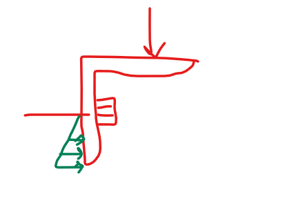
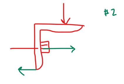
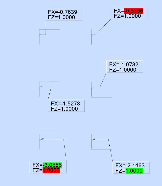
it's called "heel and toe", also "tension fitting". it's how the angle reacts the moment being applied to it (by the offset load). It should be apparent just by looking and thinking (sorry, that came out snittier than I meant).

neither sketch is a free body ... where's the shear reaction, to the applied load ? where's the balancing tension load (in 1, like it is in 2) ?

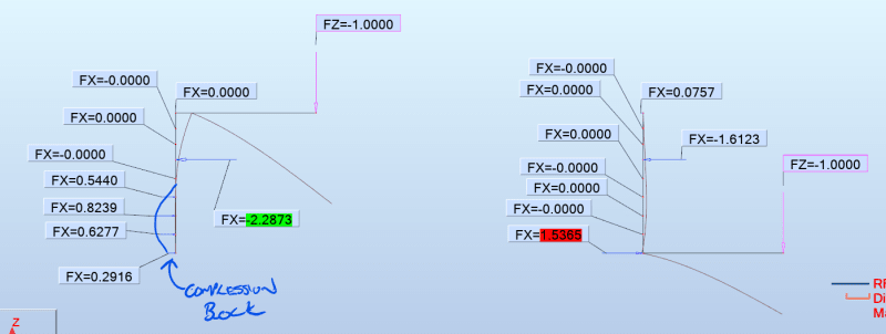
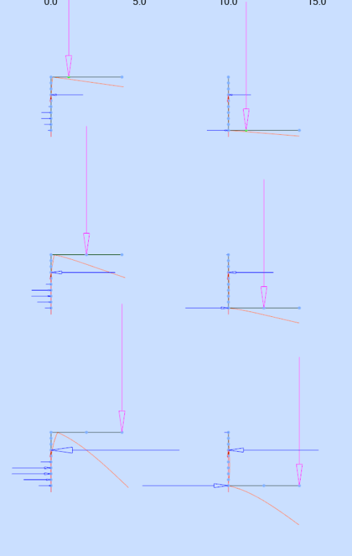
There are a host of practical reasons why one and not the other. 1 is more "real world", the load causes the "toe" of the angle to dig in while the "heel" lifts. It's reasonable to see this as a linear pressure/force. It assumes a "sufficiently stiff" flange. As the flange yields the loading drifts to the tip of the toe, your 2. because the fastener will experience tension loads, it is reasonable (and proper design would have it) that the bolt is preloaded (so it doesn't gap under load and the angle is sufficiently stiff in practice). So now there's a pressure across the base of the flange, which will be relieved to react the moment (the uniform preload pressure is reduced on one side and added to on the other). A lot more analysis ... "truth" is like that.

Of course, anything you're that concerned about the loading then you should add a stiffening web (to relieve the flange bending).

"Hoffen wir mal, dass alles gut geht !"
General Paulus, Nov 1942, outside Stalingrad after the launch of Operation Uranus.
 
Is the top of angle connected to a slab such that it can't move to the right? If so, you'll need the restraint force from the slab in the FBD. There might not be any tension on the anchor.
 
I am going to assume for the purpose of this discussion that the vertical leg of the angle is installed tight against a concrete surface.
Screenshot_2023-02-23_213832_yuylb7.png

Horizontal Reactions, applied load, and displaced shapes

The assumed triangular shape of the compression block is an approximation of the actual resulting compression field.
The orientation you have depicted I call the "weak" orientation as you are resisting the prying action with the relatively flexible vertical leg. I tend to prefer the condition on the right in my image which I dub the "strong" position as the stiffened heel results in a more localized compression field giving a larger moment arm between the resultant and the anchor tension.
 
Thanks Celt... I generally apply the point of loading on the angle near the support surface because when the toe of the angle deflects, the load will move further towards the back support. Can you run the same model with a relatively rigid load being applied 1/2 an inch from the back face?

-----*****-----
So strange to see the singularity approaching while the entire planet is rapidly turning into a hellscape. -John Coates

-Dik
 
Here you go Dik:
Screenshot_2023-02-24_002018_a4rko3.png


Anchor Tensions:
Top 1/2" from heel to load point
Middle 1 1/2" from heel to load point
Bottom load at tip of toe
L3x4x3/8 LLH (Long Leg Horizontal)
1/2" Anchor rod 2" up from the base ( k[sub]approx bolt[/sub] = AE/L = (pi*(.5/2)[sup]2[/sup] in[sup]2[/sup] * 29000 ksi) / 6 in = 950 k/in (Tension only), assumed as a rigid pin for vertical support)
5,000 psi concrete as the backup material (equiv. compression only springs, k[sub]approx[/sub] = f'c/0.003 = 5,000/0.003 = 1666666.66 lb/in = 1666.67 k/in)
Screenshot_2023-02-24_002230_cuub3k.png
 
Thanks Celt... what program are you using to develop these?

-----*****-----
So strange to see the singularity approaching while the entire planet is rapidly turning into a hellscape. -John Coates

-Dik
 
Autodesk Robot but could do the same thing in any program that lets you assign compression or tension only springs. RISA, Visual Analysis, RAM Elements are a few others I know off hand.
 
Thanks... been using that approach for shelf angles for 50 years and nothing has fallen off...

-----*****-----
So strange to see the singularity approaching while the entire planet is rapidly turning into a hellscape. -John Coates

-Dik
 
Yeah shelf angles seem to have some things that work out in their favor like the veneer reaction moving inward as the leg deflects ( as you noted already), the veneer tending to self span to the anchor locations rather that actually load the span of the shelf angle, etc.

Structure Mag had a good article in the past: Link
 
can you apply preload ?

"Hoffen wir mal, dass alles gut geht !"
General Paulus, Nov 1942, outside Stalingrad after the launch of Operation Uranus.
 
rb1957:
I believe the software has that capability but I'm not currently familiar with their process I need to get into the manual and read up on it. If I get some time over the weekend I'll follow back.
 
Celt83, can you add a fake member for the fastener and give it a temperature decrease, or give it a member length error? Either of those should accomplish the same thing as preloading.
 
271828:
yup good ideas, that's part of what I need to look into their manual for, many things in Robot are not done the way you'd expect.
 
damn ! sorry, didn't mean to make you open the manual !! (c'mon, smile)

"Hoffen wir mal, dass alles gut geht !"
General Paulus, Nov 1942, outside Stalingrad after the launch of Operation Uranus.
 
man, you need help !

"Hoffen wir mal, dass alles gut geht !"
General Paulus, Nov 1942, outside Stalingrad after the launch of Operation Uranus.
 
Status
Not open for further replies.
Back
Top