Eng-Tips is the largest engineering community on the Internet

Intelligent Work Forums for Engineering Professionals

Tertiary Through Fault Effects on Transfomer Life 2

Status
Not open for further replies.

Mbrooke

Electrical
Nov 12, 2012
2,546
0
0
US
Does anyone have an documents or data regarding increased failure rates of interconnecting transformers (345-138, 230-115kv, ect) where the tertiary is used for subtransmission/distribution?

In some parts of the world this is very common while in other parts there are claims that this results in increased wear on critical assets.
 
Replies continue below

Recommended for you

I don't have any specific data, but damage from through faults is generally considered cumulative, hence the Frequent vs Infrequent distinction in ANSI C57. If the tertiary is brought out and used for distribution, I can certainly believe that the transformer will see many more through faults during its lifetime, so some statistical loss-of-life seems completely believable. At first blush, it seems false economy to try to take advantage of the tertiary for the mundane job of 15 kV distribution in an expensive, long-lead high-voltage transmission system transformer.
 
Yup, more thru faults and I'd assume reduced life but I'm not finding any papers or in depth research on the topic. In fact in one POCO around me there is a debate it- but its just that- a debate.


If reduction is negligible, why go through the trouble with 3 extra 60MVA transformers, work, wiring, relaying, space, maintenance, ect?
 
I have been working with several utilities that have autotransformer with tertiary winding with long term performance without evidence of any life reduction. In fact, many transformers have been passing the useful life expectancy over 30 to 50 years in service.

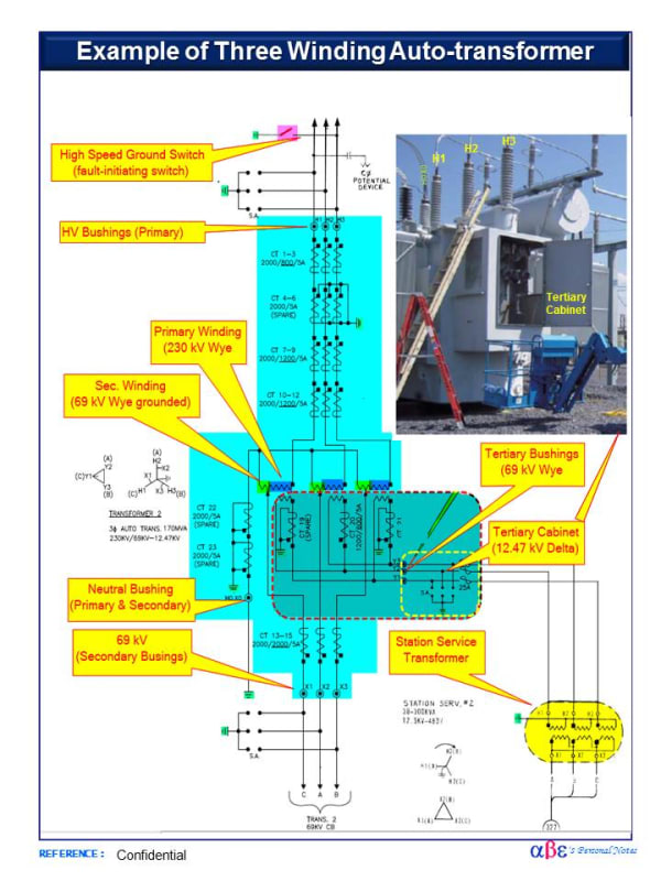
The tertiary of the transformer is in delta rated for a full BIL that made the SLG less prone to cause failure on the transformer.

Tertiary_Transformer_2_pxqzwq.jpg
 
@Cuky: are these tertiary wingdings used to supply overhead lines? I'm sorry if that wasn't obvious in your reply. My bad.
 
Mbrooke, the tertiary winding in those applications are feeding the substation MV auxiliary power.

Occasionally, some utilities choose feed 34.5 kV with overhead distribution/sub-transmission lines.
 
I see Auto's w/ Tert feeding 25-35kV Station power often. Nearly all of it is UG to 500-1500kVA Station service pad mount gear.

There is a station not too far from me, a big one, 345/138 and a ton of 25kV distribution. The two 500MVA autos show evidence of having their 25kV tertiaries connected in the past.

I asked about this and apparently these xfmrs were connected to the OH distribution system years ago. Numerous distribution faults eventually caused one of the units to fail prematurely. I was told that the Mfg informed the utility not to do this anymore as the units weren't designed for this (bracing). Both units now have the TV disconnected and the distribution is fed from 138/25kV units now.

I know when the system was using the TV, regulation wasn't great and several large cap banks served as regulation help.
 
How bad was no load to full load regulation and why?

Can bracing be added during manufacturing so that the unit can withstand repeated through faults? And for how much cost?
 
Our experience with voltage regulation on the tertiary winding is different particularly for existing old units in operation with LTC. Tertiary winding is usually designed to near 1/3 the total capacity of the main winding resulting in an oversize winding for the load connected. This winding not only helps to damps the effect of the third harmonic but also can effectively reduce the overall zero-sequence impedance and therefore alleviate the overvoltage problem during a ground fault.

There are no obvious benefits to operate unloaded the tertiary winding since will be a tendency to increase the temporary overvoltage (TOV) requiring to have one of the corner deltas permanently grounded. Otherwise, the full side surge arrester in the tertiary winding will be at high risk of failure with a potential thermal runaway situation that can no longer support even MCOV and will cause more damage than benefits.

I do not see a problem to recommend existing tertiary winding to supply station service load, capacitor, or reactive power control. However, caution should be exercised to provide large power blocks from the tertiary winding to compromise the system reliability. For a new transformer design, there are other options that should be explored.
 
By reliability do you mean breaker failure removing a whole unit or actual degradation of the transformer via through faults?

 
The autotransformer will survive a SLG on the delta side but this could escalate to an LLG fault on the tertiary forcing to trip the entire unit.

For that reason, a large tertiary distribution system is weaker than an individual two winding source.
 
I'm confused... Can you draw the scenario you have in mind? Are you saying a 3 phase fault will cause a healthy tertiary to fail?
 
No, what we want to express is that tertiary connected to a large distribution system are more exposed to failure to a SLG fault up to here no much happen perhaps an alarm. However, if a LLG fault happens after that, the protective device will trip the entire unit. In this case, a large part of the system will be out or operated with one source impacting the system reliability.

If there is an important load or sensitive load, other options than the tertiary source should be considered.
 
There are some older threads on this site about tertiary windings. If I recall correctly, some of the previous discussion included:
1) Some utilities stopped using tertiaries as the steel core material got better.
2) The typical output voltage range on tertiary windings be quite large, and is influenced by flows on the primary and secondary windings. The voltage regulation will depend on the exact arrangement of the primary, secondary, tertiary and LTC windings.
3) Even if the tertiary is not used for load, it can be useful to have tertiary bushings installed for insulation testing purposes. Unfortunately, bringing out the bushings also increased the likelihood someone will connect load to it.
 
@Cuky: I plan on a zig-zag grounding transformer. With Spacer cable there is no longer any need/benefit from operating systems ungrounded or grounded through a Peterson coil. So the first fault will produce large current flow.

There will be a breaker on the tertiary, as well as the bus supply distribution.

So only in extreme cases will the entire auto need clearing.
 
@Bacon: I know of some POCOs who will only bring out two of the leads for testing, put a strap across it (brocken delta) and then ground it. I guess that makes a good deterrent.
 
A tree branch contacting untracked spacer cable will not create high fault currents requiring trip and reclose (or line lockout) achieving the same if not greater level of service continuity as an ungrounded system. As a result is not necessary to design and build a more costly ungrounded system (1.73x insulation).
 
Status
Not open for further replies.
Back
Top