I'm not sure where else to post this, so I'll post it here.
I am putting together a test kit that will go in a vehicle for on track testing and have run into some issues. A former co-worker put together a nearly identical kit some years ago, and it's still in use. I assume it works, but have not worked with personally. That equipment is at a track in Arizona, I am in Michigan so I can't inspect it in person.
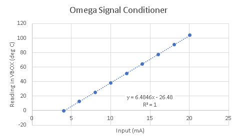
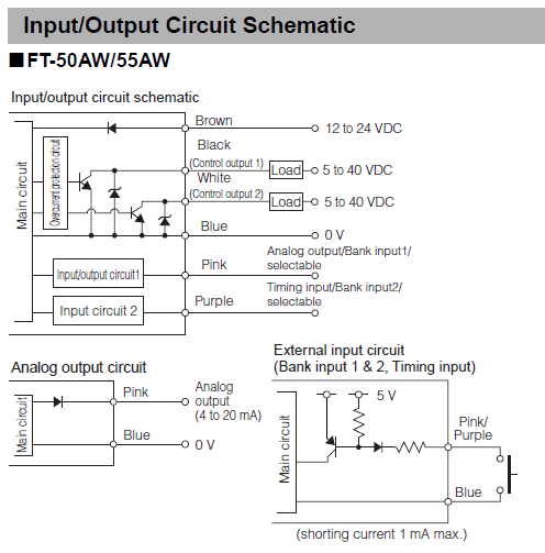
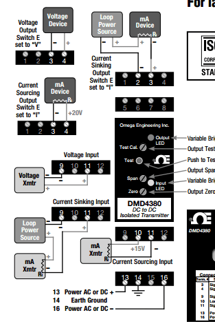
With that out of the way, this equipment is using a VBOX3i as it's base, and i'm sending some analog signals to it. The problem I'm having is with some radiation temperature sensors (two of each: Keyence FT-H30 sensor head with FT50-AW amplifier). These sensors will read the temperature of surfaces they are pointed at, and output a 4-20 mA signal. Problem is, the VBOX analog inputs can't read a current signal, they need a 0-5V signal. So the signal is sent to a signal conditioner (Omega DMD4380) for conversion.
The sensor amplifiers have a display, and when the sensor heads are pointed at the same surface, they read within about a degree of each other. When I probe the current output from the sensor amplifier to the signal conditioner, the current matches expected output perfectly, based on the display on the sensor amp. Yet when I probe the voltage on the other side of the signal conditioner, the incoming current has not be correctly translated into a voltage signal. The signal conditioners have a number of switches on the side that allow you to configure the input and output ranges. I have checked the charts and switches at least a dozen times, I am 100% certain they are set correctly. I've also calibrated and checked the zero and span several times (built a calibration device with a 24v power supply and a handful of resistors to simulate the 4 and 20 mA signals). I called Omega and described my problem, they seemed to think I had done everything right, and they would be willing to inspect my signal conditioners, but that's a lot of down time... What's going on here? is there some sort of incompatibility between my sensor and signal conditioner? Did some component inside the conditioner get fried?
----------------------------------------
I could get so much done if I didn't have to go to work
I am putting together a test kit that will go in a vehicle for on track testing and have run into some issues. A former co-worker put together a nearly identical kit some years ago, and it's still in use. I assume it works, but have not worked with personally. That equipment is at a track in Arizona, I am in Michigan so I can't inspect it in person.
With that out of the way, this equipment is using a VBOX3i as it's base, and i'm sending some analog signals to it. The problem I'm having is with some radiation temperature sensors (two of each: Keyence FT-H30 sensor head with FT50-AW amplifier). These sensors will read the temperature of surfaces they are pointed at, and output a 4-20 mA signal. Problem is, the VBOX analog inputs can't read a current signal, they need a 0-5V signal. So the signal is sent to a signal conditioner (Omega DMD4380) for conversion.
The sensor amplifiers have a display, and when the sensor heads are pointed at the same surface, they read within about a degree of each other. When I probe the current output from the sensor amplifier to the signal conditioner, the current matches expected output perfectly, based on the display on the sensor amp. Yet when I probe the voltage on the other side of the signal conditioner, the incoming current has not be correctly translated into a voltage signal. The signal conditioners have a number of switches on the side that allow you to configure the input and output ranges. I have checked the charts and switches at least a dozen times, I am 100% certain they are set correctly. I've also calibrated and checked the zero and span several times (built a calibration device with a 24v power supply and a handful of resistors to simulate the 4 and 20 mA signals). I called Omega and described my problem, they seemed to think I had done everything right, and they would be willing to inspect my signal conditioners, but that's a lot of down time... What's going on here? is there some sort of incompatibility between my sensor and signal conditioner? Did some component inside the conditioner get fried?
----------------------------------------
I could get so much done if I didn't have to go to work