Eng-Tips is the largest engineering community on the Internet

Intelligent Work Forums for Engineering Professionals

  • Congratulations waross on being selected by the Tek-Tips community for having the most helpful posts in the forums last week. Way to Go!

The clear story on clerestory window framing 1

Status
Not open for further replies.

StrEng007

Structural
Aug 22, 2014
486
0
0
US
Sorry for the subject title...

After reading through some existing posts on clerestory framing, I'm taking a different approach to the discussion.

The consensus seems to be that most clerestory framing is achieved through continuous columns that support gravity and acts as a lateral cantilever such as shown in the the image below:
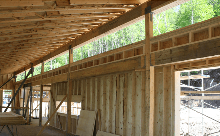
Screenshot_2024-03-05_093511_mpcnbf.png

Photo 1


Here is another example.
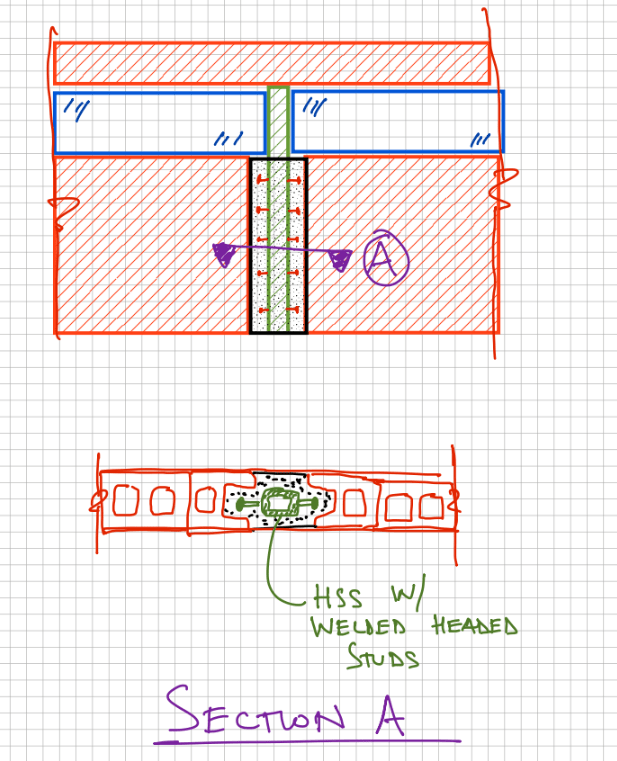
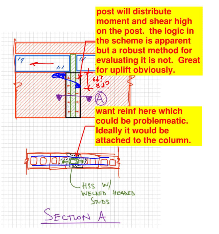
To me, it looks like the clerestory window is framed with individual shear wall panels that sit on top of a transfer beam. Transfer beam takes gravity and lateral (as a strut) and must be pulling the lateral from the connection at the left edge.
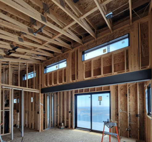
Screenshot_2024-03-05_093403_dknnmo.png

Photo 2


I believe this one is a moment frame.
Due to lack of vertical and lateral continuity along the field, this has to be a moment frame, or so you'd hope right?
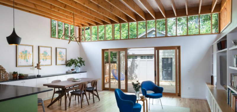
Screenshot_2024-03-05_093030_z5icnf.png

Photo 3

[highlight #FCE94F]Now for my questions:[/highlight]
1.Does anyone have reference to any design examples, books, or technical papers that discuss clerestory framing?
2.Does anyone have recommendations for achieving the same effect with a masonry/concrete shell structures?
2.1 Using concrete moment frames?​
2.2 Using concrete shear walls with full height steel tubes (similar to shown for wood)​
3.For the type of framing shown in Photo 1, I've read that all columns need to deflect at the same rate in order for the system to be effective. What is the problem if they don't? The way I see it, each column supports it's own tributary lateral load, so the spacing of the columns will determine how much lateral forces is imparted. Are we really selecting different columns at each location for the sole purpose of deflection?
 
Replies continue below

Recommended for you

1. "The Analysis of Irregular Shaped Structures - Diaphragms and Shear Walls" by Malone is probably your best bet. It's one of the few books that gets into the lateral analysis of non-simple buildings, like what we're faced with on real projects.

2. I don't have specific knowledge with this, although I think I would use a similar analysis method as if it was wood/steel framed.

3. Concerning the comment "all columns need to deflect at the same rate in order for the system to be effective," my take on that would be:
[ol A]
[li]In the context of Photo 1, due to the stiffness of the roof diaphragm, it seems unlikely that one column would deflect (any appreciable amount) more than another because the diaphragm will move as a single rigid piece (for the most part) dragging the columns with it. So, a better way to put it might be that all columns must deflect the same amount.[/li]
[li]If all columns must deflect the same amount, then for the load to be shared equally between them (based on tributary area), then the columns should all have equal stiffness. If one column was significant stiffer, like if the columns in Photo 1 were all 2x6 studs, except the middle one was a W12x30 steel section, the roof diaphragm loads would almost entirely go to the W12x30. The columns would all deflect the same amount in terms of the overall model though. [/li]
[li]I think what that comment perhaps means is that if you were to simply look at the tributary load to each column and then analyze each column independently, for the overall model to be correct, it would be necessary for all column deflections to match. Technically, you could still do the analysis this way, but if the deflections didn't match, you would need to adjust the load going to the columns based on their stiffnesses, meaning that a simple tributary area approach is no longer appropriate.[/li]
[/ol]

Hopefully that explanation helps. (It ended up more long-winded than I hoped.)
 
I feel that using a three sided, "storefront" lateral scheme makes sense in many cases. Often, whatever you do at the clear story, short of filling some of it in, the result will be a four sided VLFRS scheme that can't compete with the more realistic three sided one from the perspective of stiffness.

The three sided thing is problematic in seismic country because of the torsional eccentricity that the system implies. When that is a concern, moment frames on the open side are often considered a desirable solution. They probably don't really engage until things get pretty ugly but, at the least, they're there when things do get ugly.
 
KootK,
I've got a request for clerestory windows on multiple sides of the structure. This would invalidate the 3-sided diaphragm... so am I back to cantilever columns? My shell is masonry and I can sneak some vertical steel columns into the wall to recreate Photo 1 for hurricane territory.
 
Eng16080 said:
then for the load to be shared equally between them (based on tributary area), then the columns should all have equal stiffness.
So the next question is: if we can say the diaphragm moves as one piece, then we could put any number of columns at non-equal spacing and they'd each load share somewhat equally if they all have the same stiffness.

In Photo 1 the header is pretty stiff and I expect it would move as one piece. Does this apply to a simple top plate connection as well (something much weaker in stiffness)?

My understanding with flexible diaphragms is that the distance between each of those columns would behave like a collector element. Therefore, the lateral loads imparted to the columns wouldn't be the same. I'd have to put pen to paper and doing some calculations to gather my thoughts on this. I'm not saying I disagree with you, I'm saying I don't have a solid opinion on this yet.
 
StrEng007 said:
This would invalidate the 3-sided diaphragm... so am I back to cantilever columns?

So it would seem.

StrEng007 said:
I've read that all columns need to deflect at the same rate in order for the system to be effective. What is the problem if they don't?

I think that this is just an awkward expression of "stiffness matters". If some of the cantilever posts wind up much stiffer than others, for any number of reasons, then the assumption of uniform load distribution will be false. And that can have poor consequences if there are any non-ductile aspects to system failure.

StrENG007 said:
My shell is masonry and I can sneak some vertical steel columns into the wall to recreate Photo 1 for hurricane territory.

That sounds alright to me other than the fact that you'll have high demand anchorages at the post bases with both shear and moment. I don't have great confidence in exotic anchorage to masonry. Any chance you could get a CIP capping beam for the top couple of courses just to facilitate a clean anchorage condition?

 
KootK said:
I don't have great confidence in exotic anchorage to masonry.
Neither do I.

This is my approach. I've been able to get the shell contractor to do this without complaints in the past.

Screenshot_2024-03-05_133730_rspf9q.png
 
StrEng007 said:
if we can say the diaphragm moves as one piece, then we could put any number of columns at non-equal spacing and they'd each load share somewhat equally if they all have the same stiffness.
Yes, in that case I believe they would all have to take the same load. Otherwise, they would deflect differently.

StrEng007 said:
In Photo 1 the header is pretty stiff and I expect it would move as one piece. Does this apply to a simple top plate connection as well (something much weaker in stiffness)?
I would think so, as long as the wall is connected sufficiently to not tear apart, which could happen if the top plate is acting as a collector element and is not properly designed (connected).

StrEng007 said:
My understanding with flexible diaphragms is that the distance between each of those columns would behave like a collector element. Therefore, the lateral loads imparted to the columns wouldn't be the same. I'd have to put pen to paper and doing some calculations to gather my thoughts on this. I'm not saying I disagree with you, I'm saying I don't have a solid opinion on this yet.
Again, if we're saying the columns are all equal stiffness, then the load to each would have to be the same. That load would have to get to each column through a valid load path, basically with collectors. The most optimal layout would likely be with the columns evenly spaced or nearly so. If all the columns were at the left side, for example, there would need to be a collector getting the load from the right side into the columns at the left. The collector force would be at a maximum where it hits the first column, and from there, it would drop at each column as the load is being dissipated.

Your "Section A" detail above looks reasonable to me. I've used a similar detail before with an I-section (except in a wood wall not masonry).

One other thing: In designing the overall wall, be sure not to neglect out-of-plane wind forces. I find that this aspect of the design is often overlooked.
 
With cantilever column schemes, the R value goes down significantly for seismic, like R=1.5 for timber. Not a big deal if seismic doesn't control, but it might make it control.
 
Eng16080 said:
One other thing: In designing the overall wall, be sure not to neglect out-of-plane wind forces. I find that this aspect of the design is often overlooked.
Yes, good point. What I've done in the past is provide a concrete sill beam at the bottom of the clerestory window. Wall is designed to span vertical. Sill beam spans horizontal and reinforcing engages at the steel column/studs with hooked bars at the solid concrete band, or a I'll place welded couplers on the tube to receive rebar. As Koot mentioned, not really a straight forward way to analysis this but I've made sure to apply some logic per ACI 318.

KootK said:
want reinforcing here which could be problematic
Regarding the horizontal joint reinforcing... I'd typically interrupt the reinforcing at the location of the tube. Each of the CMU segments on each side would be treated as individual shear wall elements. They get their own end zones for vertical steel reinforcing (shear wall chords). Lateral load is distributed to the shear walls via the horizontal sill beam (similar to a reinforced concrete tie beam) that I mentioned in response to Eng16080.

I showed welded headed studs along the entire vertical length... after reviewing my details, I usually have studs in that end zone that you showed at the top of the wall, not the full height of the embedded column. Is it the most sophisticated method? Probably not

KootK said:
Great for uplift
That's a huge part of this solution.

milkshakelake said:
the R value goes down significantly for seismic
No seismic where these jobs are. Most likely I'm doing 175MPH Exp D. Wind ALWAYS governs.
 
Status
Not open for further replies.
Back
Top