SprinklerDesigner2
Mechanical
I've just completed a project where the issue of having a shut off valve in the fire department connection line has come up.
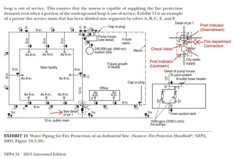
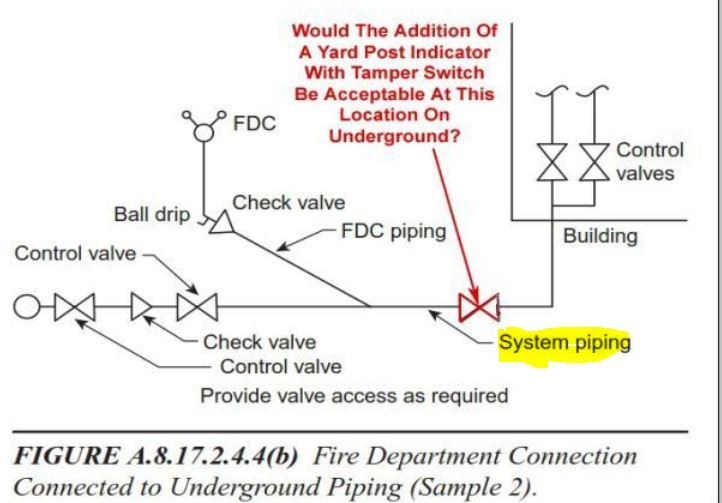
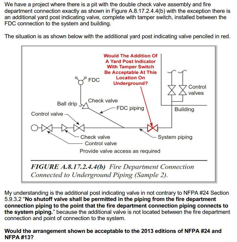
What I have is exactly the situation presented in FIGURE A.8.17.2.4.4(b) except I photo-shopped a yard post indicating valve between the 8"x8"x4" tee in the pit and flange and spigot piece in the building.
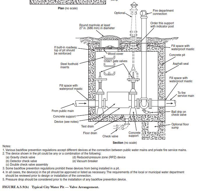
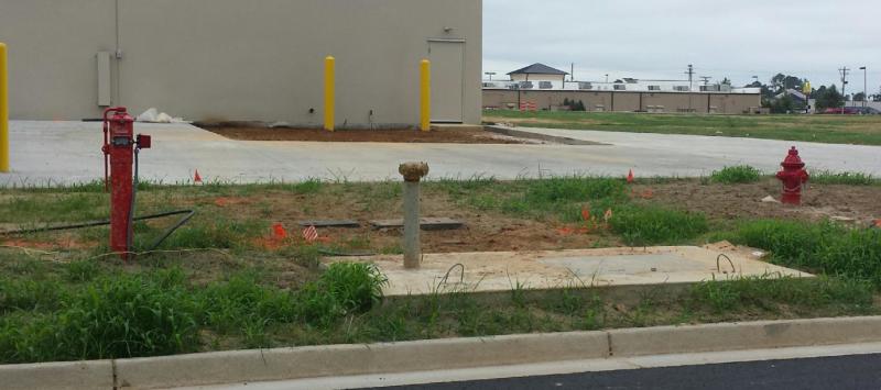
Below is photo of actual project where water enters the pit from the right (the pumper hydrant you see is upstream the pit), travels through a large water meter followed by a double check where with O.S.&Y's followed yet again by an 8"x8"xx4" flanged tee that has a 4" check valve between the 8" line and FDC. Of course there is not a shut-off valve in the 4" line between the FDC and 8"x8"x4" flanged tee.
From the pit there is a single yard post indicator valve with tamper switch, this is the red PIV I photo-shopped into the figure, whereupon the 8" underground continues on to feed a manifolded sprinkler system serving the building in the background.
PS I already know the answer, it's fine as is, but I am asking for the clarification of others. I think what it comes down to is what is the definition of the line between the FDC and system connection?
Thank you for your input.
What I have is exactly the situation presented in FIGURE A.8.17.2.4.4(b) except I photo-shopped a yard post indicating valve between the 8"x8"x4" tee in the pit and flange and spigot piece in the building.

Below is photo of actual project where water enters the pit from the right (the pumper hydrant you see is upstream the pit), travels through a large water meter followed by a double check where with O.S.&Y's followed yet again by an 8"x8"xx4" flanged tee that has a 4" check valve between the 8" line and FDC. Of course there is not a shut-off valve in the 4" line between the FDC and 8"x8"x4" flanged tee.
From the pit there is a single yard post indicator valve with tamper switch, this is the red PIV I photo-shopped into the figure, whereupon the 8" underground continues on to feed a manifolded sprinkler system serving the building in the background.

PS I already know the answer, it's fine as is, but I am asking for the clarification of others. I think what it comes down to is what is the definition of the line between the FDC and system connection?
Thank you for your input.

