Design from which point of view? Pressure design? Such methods are normally outlined in the design codes acc. which the piping is designed. See e.g. ASME B31.3 para 304.3.
Ahmedan47:
Are you talking about the actual design, that is, material selection, thickness, etc. and stress analysis and welding design; or are you talking about the layout of the various pieces so they fit together and can be welded? This layout, cutting and fitting can be done on two pieces of pipe to be fit together, or on two pieces of plate/sheet which must then be formed and made into pipes which will then fit together? They are two very different animals, sorta encompassed by the term design.
Thank you XL83NL and dhengr for your reply >
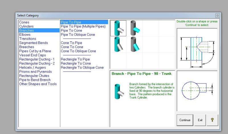
my question was about the intersection of pipes in fittings >> e.g if i want to make a 10 inches branch in a 16 inches header with 45 degree .. how to cut the pipes to make perfect mesh between the two pipes
this method is about dividing the perimeter of the pipes into segment and then do some calculations .
i want to learn this method
It was done with pencil and paper for many years, before computers and AutoCAD.
It requires no calculation, just accurate drawing and transfering of dimensions or template over the sheetmetal to be cut and rolled or over the surface of two pipes.
In the case of pipes, the thickness of the walls must be considered, as well as the angles of the cut for a best welding.
I am still trying to figure out ahmedan47's objective, so a sketch with proper labels would have been a better choice. I sensed though that in order to learn the development procedure from a 3D drawing to a 2D drawing involving pipes, ahmedan47 should take a course in descriptive geometry as all CE's and ME's of my generation had to take in college.
thank you guys .. all of your comments are very appreciated and helpful
thanks alot .
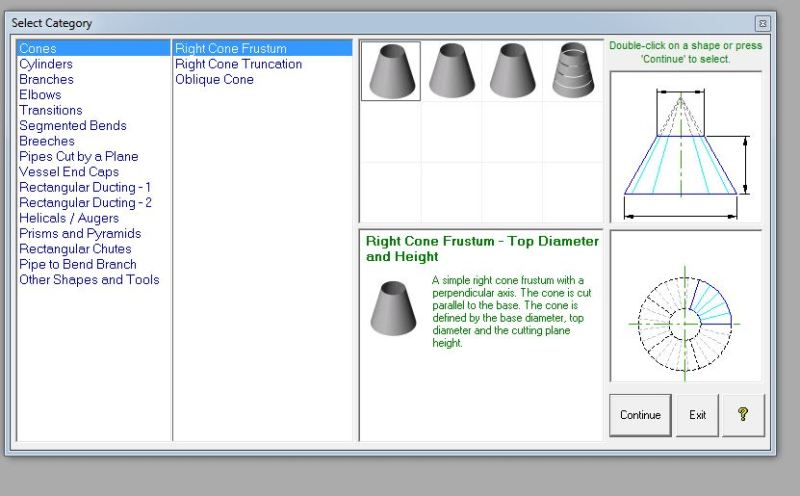
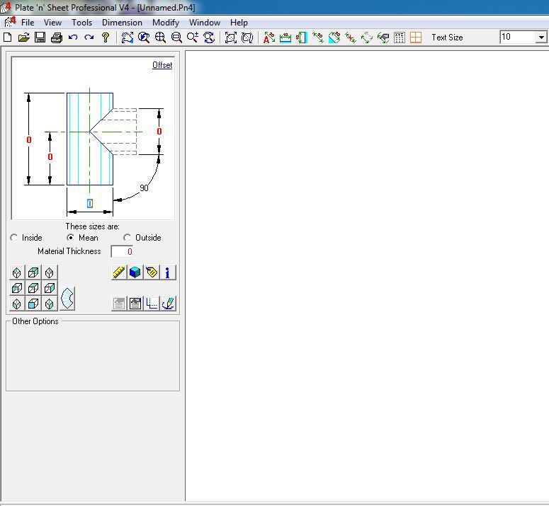
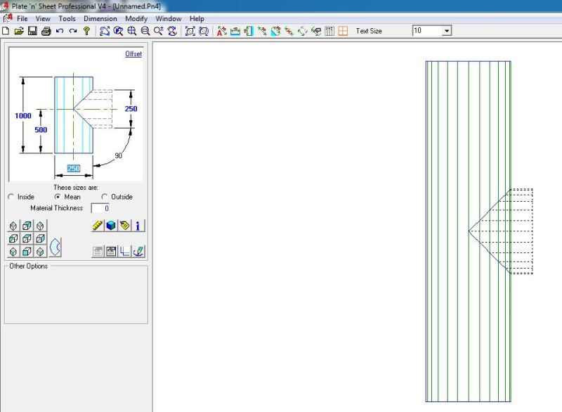
Dear chicopee .. i guess i wasn't that good in showing my point .. to fully get my point use the ( Plate n Sheet ) software .. it's a very small program .. i just wanna do what it does manually .. thanks alot sir
If the question was purely about shaping the branch then the OP's first sketch covers it. I remember many years ago learning this during apprenticeship in fabrication shop where we drew on special paper then transferred to pipe to be shaped and I would guess it would be in Pipefitters Handbook.

![[openup]](/data/assets/smilies/openup.gif "[openup] [openup]")