-
1
- #1
Dear forum,
When discussing technical problems, do you ever consider what direction the piping profession will take in the near future? We are at the beginning of a new year so I thought let me break a lance on this topic. Don't think after reading that I'm against new technologies, on the contrary, but the balance can also go the wrong way. I would also like to hear what you think about it.
Long, long ago with a drawing board and A1-format polyester calque, cupboards full of technical documentation and a lot of clutter on your desk. If you went to the site to take measurements, you just registered at the gate and sometimes without a work permit you got to work. Good that this is all over, isn't it? The world is changing fast and that's a good thing otherwise we would still be walking around in bearskins. In the 80's the first PC's with drawing programs came on the market. These were so expensive (Intergraph) that designers had to work shifts to cover the costs. These first CAD operators often came from behind the drawing board with a considerable amount of experience in piping design. All the technical information was in their heads and otherwise in the technical manuals and supplier documentation in the department. Because nowadays a paperless desk is the norm, the information must be digitized on the one hand and traceable on the other. The latter sometimes causes problems (who doesn't know it, where was that again?).
Profile of a piping (design) engineer.
In a technical education, students often work with Autocad, Revit and Inventor. Many students then opt for the civil and mechanical direction in engineering. In general, you don't consciously choose piping, but you play a role in it in one way or another. There is a difference in way of thinking and mentality between piping and mechanical. Piping thinks in millimeters and mechanically in hundredths of a millimeter. Piping "sticks" components together and mechanical creates something from scratch. Personally I think; Piping is more of a cowboy (more coarse) and mechanical more refined. For that reason, women more often opt for civil, structural or mechanical. Good piping engineers are hard to find, you must have an affection for the piping profession, and a little knowledge of process engineering (hydraulics, etc) is recommended. Because the piping department is usually leading in a project, the lead piping must also be aware of what is happening in the other disciplines. In short, the piping department is a spider in the web, you have a "get and bring duty" and you have to be comfortable with that.
Advice to a junior
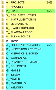
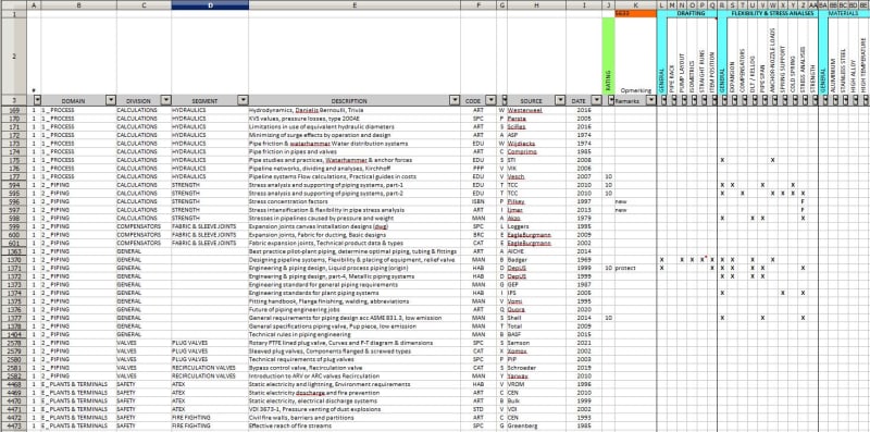
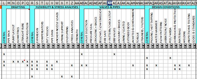
When I started in the piping department as a draftsmen (40 years ago), it was not a conscious choice. I came from assembly and was a maintenance engineer for compressors. A difference of opinion with my supervisor made me decide to work at an engineering office and there happened to be room for piping (after all, I had experience with piping). To learn the basics I did a written piping course and I was always looking through the technical information (catalogs, manual, etc). This is what I have always done to this day, taking information and copying many topics. When I encountered a technical problem, I first tried to solve it myself by diving deep into the matter. Due to this spin-off effect, I now have 17 Gb (5700 pfd's) of technical information, well-arranged, let the paperless desk come. Whenever you see a pipe- or pump line-up you should always ask yourself why it was done that way and how you would have done it in that case. An important point to start as a junior is to familiarize yourself with typical expressions and abbreviations in the piping. This is mandatory for every design engineer, because the piping world depends on abbreviations. A pipe spec or MTO will otherwise become unreadable. The abbreviations that I see on pipingdesigner.com are not that clear to me, so I have added an alternative as an attachment.
Try to go to the site as much as possible, then you will learn more than from a 3D scan. For design engineer; make a study of a piping part for a presentation with your colleagues. Take a bend for example. Often there is confusion of tongues when talking about 1.5D and LR elbows. Then you have to realize in which system you are working, imperial or metric. Try to understand something about hydraulics, what is the effect of the flow on a butterfly valve behind the bend. Also realize that you can save the stress department a lot of work if you look at the flexibility of the piping yourself. Solving simple flexibility problems is part of the job of a design engineer.
The Eng-Tips posts repeatedly ask what a good 3D piping software is. Well, there isn't and there isn't a bad one and everything is very expensive. I have been working with drawing programs since ACAD12, I have written a 2D parametric piping application within Autocad myself (3D software was not yet available). Nothing comes out of a computer more than what you put into it yourself. Take a look at the forum sites of Plant 3D, Cadworx or E3D, where things are discussed or what is good and what is not good. Isometrics from a 3D package are often to cry. TIP, try setting up an isometric by hand yourself. You will have to learn that if you have to measure an existing pipeline on site visit with a sketch pad. Well, that was a long story with a slightly different approach. Try to think outside the box.
Information & internet
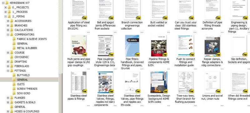
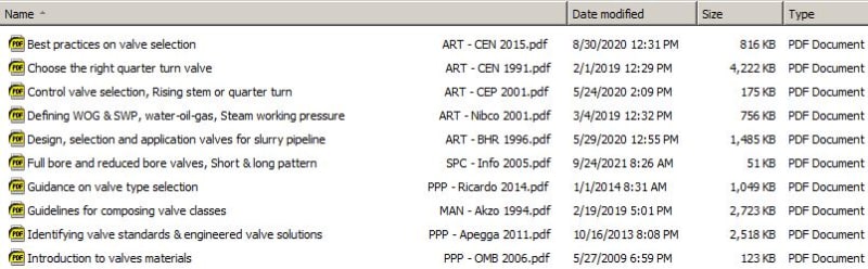
The piping department is dependent on technical documentation. Apart from standard fittings as described in the ASME and EN standards, we deal with valves, actuators, filters, strainers, bellows, pump tanks, etc. You name it. A renowned engineering firm should have these standards in house, nowadays digital. All other information must come from manufacturers or suppliers. Valves have standard lengths, so no problem. Detailed information will not be provided until the order has been placed. If all goes well, the piece of equipment can also be obtained digitally, for example. However, this is 9 out of 10 times a different (digital) format than the piping layout. Then the assemblies where everything is in it, down to all the nuts and bolts. This can also occur with valves, pipe supports, etc., which can be supplied digitally. To ensure that the drawings do not become too heavy (many Mb in size), these files can also be linked to the source drawings (Xrefs). I've experienced many times what it's like when you open a drawing and half of it isn't there. For example, whether the link is missing or the linked drawings were not sent. Because of carelessness, humans are the weak link here. The following about the missing link; The posts also often contain a link to an internet site, after a few years it no longer works (error 404).
In addition to my digital knowledge base, I also have paper catalogs, which you got if you had regular contact with suppliers. When I compare the contents of catalog with the contents of the site in question, the paper catalog is much more informative than the site catalog. I think this is done from a competitive point of view. You see more and more that manufacturers "lock" their site unless you have an account, there is no longer any question of being free.
Which persons are involved in a piping project and what is their role in this?
Within a piping project these are project manager, lead piping engineer, design engineers and drafters.
When you design an installation with a piping 3D software package, a 5th person must be added at the start-up phase of the project. Without this person (system engineer), the 3D software will not come to life. Engineers and drafters should be added to the project. Catalogs must be selected and pipe specs must be composed. A super-user can be the lead or one of the design engineers. The super-user is in close contact with the system engineer. If the project is running smoothly, the system engineer is no longer necessary. The super-user can take care.
What exactly does such a system engineer do?
He can, for example, give courses on the drafting package to drafters (juniors) just starting out. But especially at the larger engineering firms, his daily job is dealing with catalogs and pipe specs.
What are catalogs? A catalog is a large collection (database) of piping components in which the shape, dimensions and properties are described. A pipe spec (subset) can then be generated from a catalog. This pipe spec is then added to the project. There is an ASME Pipes and fittings catalog, but also the DIN catalog, Agru catalog, etc. The catalogs are “built” by an external software company, and this software company has a certain status (value added re-seller) with the software company of the 3D drawing package.
The manufacturer of piping components such as NOV, +GF+ or Victaulic gives the order (and pays) to the external software company. Now we know how the lines run and where all that “misery” comes from. As a manufacturer you are only interested in your own product, so you put your own order codes etc. in the catalog. This causes a lot of pollution in your pipe spec and MTO because there are more manufacturers that supply the same and just that other manufacturer has been chosen for your project. I've reviewed many catalogs and I didn't find them representative enough. References to international standards, incomplete diameter ranges, etc. are not handled properly. In short, I've redesigned a number of catalogs so that they are all in the same line and in order to be able to maintain better. Now I come back to that system engineer, who has to make sure that the pipe spec is complete, so also the catalog, which is often not the case. Also during a project, components often have to be made.
Rework
As a drafter or designer you are now able to put a bend or flange against a pipe and this message appears in the drawing “cannot connect components” with a series of possible causes. After all, the program is “intelligent”. You can put the bend or flange against it and it will still stay in place. So the layout looks good but eventually there will be no iso. Or an iso with the pipe and an iso with the bend. The reason lies in the fact that the ends of the pipe are provided with certain properties. If these do not match the other side, you will receive this message. Then something has to be adjusted by the super-user or system engineer. This is a regularly recurring problem that takes the engineer's time and I have a problem with that. The designer or engineer can better use this time to become proficient in real piping related problems than that software nonsense. One more poignant example to conclude my story.
In the real piping world, back to back flanges (with hubs) are no problem.
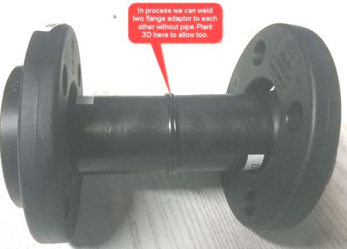
Since the existence of P3D it is not possible to make this construction . This is because the stub-end is typed as a connector and not as a flange part so the software will not accept this. So you have to put a piece of pipe in between with 2 welds. This is regularly discussed on the forums but no feedback is given. Did the P3D development team have a good piping engineer? Or do they prefer to hire more sales engineers, that sells better. Other 3D software does not seem to suffer from this, but if you have made an investment of thousands of dollars as a company, you don't just change software. And certainly not within current projects.
My conclusion is for consideration;
A- a software engineer is not a piping engineer.
a software engineer with 3 years of piping experience doesn't know much about piping.
B- piping 3D software is not an end in itself
software companies have too nice sales talk
C- general piping knowledge level of design engineers must be better
you have to constantly improve yourself and expand your skill.
On the 3D forum they called this a slip-on flanges and there was no one to correct him.
p.s Google Translate was my friend.
When discussing technical problems, do you ever consider what direction the piping profession will take in the near future? We are at the beginning of a new year so I thought let me break a lance on this topic. Don't think after reading that I'm against new technologies, on the contrary, but the balance can also go the wrong way. I would also like to hear what you think about it.
Long, long ago with a drawing board and A1-format polyester calque, cupboards full of technical documentation and a lot of clutter on your desk. If you went to the site to take measurements, you just registered at the gate and sometimes without a work permit you got to work. Good that this is all over, isn't it? The world is changing fast and that's a good thing otherwise we would still be walking around in bearskins. In the 80's the first PC's with drawing programs came on the market. These were so expensive (Intergraph) that designers had to work shifts to cover the costs. These first CAD operators often came from behind the drawing board with a considerable amount of experience in piping design. All the technical information was in their heads and otherwise in the technical manuals and supplier documentation in the department. Because nowadays a paperless desk is the norm, the information must be digitized on the one hand and traceable on the other. The latter sometimes causes problems (who doesn't know it, where was that again?).
Profile of a piping (design) engineer.
In a technical education, students often work with Autocad, Revit and Inventor. Many students then opt for the civil and mechanical direction in engineering. In general, you don't consciously choose piping, but you play a role in it in one way or another. There is a difference in way of thinking and mentality between piping and mechanical. Piping thinks in millimeters and mechanically in hundredths of a millimeter. Piping "sticks" components together and mechanical creates something from scratch. Personally I think; Piping is more of a cowboy (more coarse) and mechanical more refined. For that reason, women more often opt for civil, structural or mechanical. Good piping engineers are hard to find, you must have an affection for the piping profession, and a little knowledge of process engineering (hydraulics, etc) is recommended. Because the piping department is usually leading in a project, the lead piping must also be aware of what is happening in the other disciplines. In short, the piping department is a spider in the web, you have a "get and bring duty" and you have to be comfortable with that.
Advice to a junior
When I started in the piping department as a draftsmen (40 years ago), it was not a conscious choice. I came from assembly and was a maintenance engineer for compressors. A difference of opinion with my supervisor made me decide to work at an engineering office and there happened to be room for piping (after all, I had experience with piping). To learn the basics I did a written piping course and I was always looking through the technical information (catalogs, manual, etc). This is what I have always done to this day, taking information and copying many topics. When I encountered a technical problem, I first tried to solve it myself by diving deep into the matter. Due to this spin-off effect, I now have 17 Gb (5700 pfd's) of technical information, well-arranged, let the paperless desk come. Whenever you see a pipe- or pump line-up you should always ask yourself why it was done that way and how you would have done it in that case. An important point to start as a junior is to familiarize yourself with typical expressions and abbreviations in the piping. This is mandatory for every design engineer, because the piping world depends on abbreviations. A pipe spec or MTO will otherwise become unreadable. The abbreviations that I see on pipingdesigner.com are not that clear to me, so I have added an alternative as an attachment.
Try to go to the site as much as possible, then you will learn more than from a 3D scan. For design engineer; make a study of a piping part for a presentation with your colleagues. Take a bend for example. Often there is confusion of tongues when talking about 1.5D and LR elbows. Then you have to realize in which system you are working, imperial or metric. Try to understand something about hydraulics, what is the effect of the flow on a butterfly valve behind the bend. Also realize that you can save the stress department a lot of work if you look at the flexibility of the piping yourself. Solving simple flexibility problems is part of the job of a design engineer.
The Eng-Tips posts repeatedly ask what a good 3D piping software is. Well, there isn't and there isn't a bad one and everything is very expensive. I have been working with drawing programs since ACAD12, I have written a 2D parametric piping application within Autocad myself (3D software was not yet available). Nothing comes out of a computer more than what you put into it yourself. Take a look at the forum sites of Plant 3D, Cadworx or E3D, where things are discussed or what is good and what is not good. Isometrics from a 3D package are often to cry. TIP, try setting up an isometric by hand yourself. You will have to learn that if you have to measure an existing pipeline on site visit with a sketch pad. Well, that was a long story with a slightly different approach. Try to think outside the box.
Information & internet
The piping department is dependent on technical documentation. Apart from standard fittings as described in the ASME and EN standards, we deal with valves, actuators, filters, strainers, bellows, pump tanks, etc. You name it. A renowned engineering firm should have these standards in house, nowadays digital. All other information must come from manufacturers or suppliers. Valves have standard lengths, so no problem. Detailed information will not be provided until the order has been placed. If all goes well, the piece of equipment can also be obtained digitally, for example. However, this is 9 out of 10 times a different (digital) format than the piping layout. Then the assemblies where everything is in it, down to all the nuts and bolts. This can also occur with valves, pipe supports, etc., which can be supplied digitally. To ensure that the drawings do not become too heavy (many Mb in size), these files can also be linked to the source drawings (Xrefs). I've experienced many times what it's like when you open a drawing and half of it isn't there. For example, whether the link is missing or the linked drawings were not sent. Because of carelessness, humans are the weak link here. The following about the missing link; The posts also often contain a link to an internet site, after a few years it no longer works (error 404).
In addition to my digital knowledge base, I also have paper catalogs, which you got if you had regular contact with suppliers. When I compare the contents of catalog with the contents of the site in question, the paper catalog is much more informative than the site catalog. I think this is done from a competitive point of view. You see more and more that manufacturers "lock" their site unless you have an account, there is no longer any question of being free.
Which persons are involved in a piping project and what is their role in this?
Within a piping project these are project manager, lead piping engineer, design engineers and drafters.
When you design an installation with a piping 3D software package, a 5th person must be added at the start-up phase of the project. Without this person (system engineer), the 3D software will not come to life. Engineers and drafters should be added to the project. Catalogs must be selected and pipe specs must be composed. A super-user can be the lead or one of the design engineers. The super-user is in close contact with the system engineer. If the project is running smoothly, the system engineer is no longer necessary. The super-user can take care.
What exactly does such a system engineer do?
He can, for example, give courses on the drafting package to drafters (juniors) just starting out. But especially at the larger engineering firms, his daily job is dealing with catalogs and pipe specs.
What are catalogs? A catalog is a large collection (database) of piping components in which the shape, dimensions and properties are described. A pipe spec (subset) can then be generated from a catalog. This pipe spec is then added to the project. There is an ASME Pipes and fittings catalog, but also the DIN catalog, Agru catalog, etc. The catalogs are “built” by an external software company, and this software company has a certain status (value added re-seller) with the software company of the 3D drawing package.
The manufacturer of piping components such as NOV, +GF+ or Victaulic gives the order (and pays) to the external software company. Now we know how the lines run and where all that “misery” comes from. As a manufacturer you are only interested in your own product, so you put your own order codes etc. in the catalog. This causes a lot of pollution in your pipe spec and MTO because there are more manufacturers that supply the same and just that other manufacturer has been chosen for your project. I've reviewed many catalogs and I didn't find them representative enough. References to international standards, incomplete diameter ranges, etc. are not handled properly. In short, I've redesigned a number of catalogs so that they are all in the same line and in order to be able to maintain better. Now I come back to that system engineer, who has to make sure that the pipe spec is complete, so also the catalog, which is often not the case. Also during a project, components often have to be made.
Rework
As a drafter or designer you are now able to put a bend or flange against a pipe and this message appears in the drawing “cannot connect components” with a series of possible causes. After all, the program is “intelligent”. You can put the bend or flange against it and it will still stay in place. So the layout looks good but eventually there will be no iso. Or an iso with the pipe and an iso with the bend. The reason lies in the fact that the ends of the pipe are provided with certain properties. If these do not match the other side, you will receive this message. Then something has to be adjusted by the super-user or system engineer. This is a regularly recurring problem that takes the engineer's time and I have a problem with that. The designer or engineer can better use this time to become proficient in real piping related problems than that software nonsense. One more poignant example to conclude my story.
In the real piping world, back to back flanges (with hubs) are no problem.
Since the existence of P3D it is not possible to make this construction . This is because the stub-end is typed as a connector and not as a flange part so the software will not accept this. So you have to put a piece of pipe in between with 2 welds. This is regularly discussed on the forums but no feedback is given. Did the P3D development team have a good piping engineer? Or do they prefer to hire more sales engineers, that sells better. Other 3D software does not seem to suffer from this, but if you have made an investment of thousands of dollars as a company, you don't just change software. And certainly not within current projects.
My conclusion is for consideration;
A- a software engineer is not a piping engineer.
a software engineer with 3 years of piping experience doesn't know much about piping.
B- piping 3D software is not an end in itself
software companies have too nice sales talk
C- general piping knowledge level of design engineers must be better
you have to constantly improve yourself and expand your skill.
On the 3D forum they called this a slip-on flanges and there was no one to correct him.
p.s Google Translate was my friend.