Eng-Tips is the largest engineering community on the Internet

Intelligent Work Forums for Engineering Professionals

Thermal Loop Heat Transfer

Status
Not open for further replies.

ERSMechE

Mechanical
Aug 7, 2012
18
0
0
US
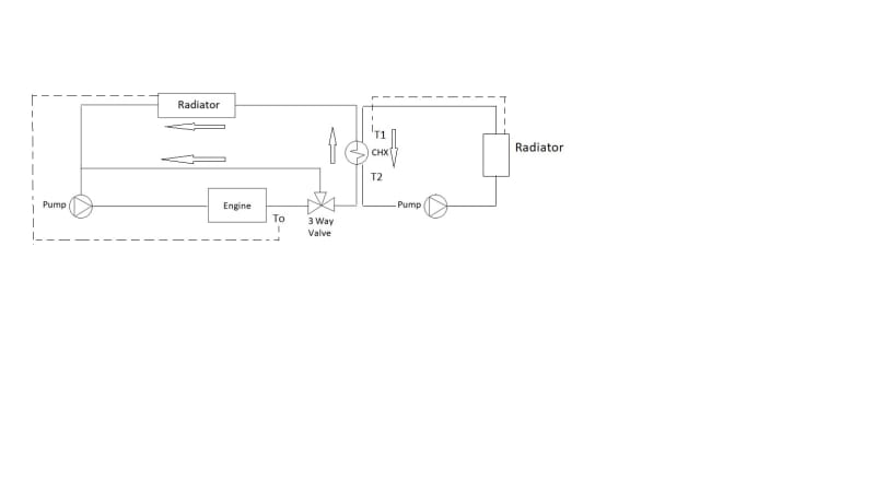
Hello, I have two fluid loops filled with the same coolant mixutre that are circulating in opposite directions. On the left side, there is an engine that is supplying heat to the coolant loop. Immediately after the engine outlet, there is a thermostatic 3 way valve that is diverting 100% of the volume flow back to the engine until the engine reaches its operating temp, To (185F). After which, the volume flow is split and coolant will flow through the outer loop as well. The outer loop has a plate and frame heat exchanger (CHX) followed by an automotive style radiator/fan combo that is electronically controlled by a sensor at To (see dotted line). On the opposite side, there is also a radiator/fan combo that is electronically set to control the temperature at T1 (see dotted line).

Our objective is to measure the amount of heat being transferred across the heat exchanger (CHX) by applying the temperature differential across T1 and T2 to formula Q=rho*Cp*V*deltaT. The radiator on the right side is not always on, when it is not, the heat is removed by the radiator in the left side loop. When the right radiator is on, the left radiator is inactive.

The problem that I am having is that when we are using the right side radiator/fan and heat is being transferred across the heat exchanger, the engine outlet temperature drops. I do not understand why this is happening. The way I am thinking about this is a closed system energy balance problem. Heat in from the engine should equal heat across the heat exchanger which should equal heat across the radiator. Can anyone help explain why the engine outlet temperature drops? Please let me know if you need any more information about the problem. I appreciate any insight that can be provided.

coolant_loop_lfinyr.jpg
 
Replies continue below

Recommended for you

I agree. The orientation of your radiator on the engine loop will make a big impact. If it is in fact horizontal and allows air to circulate by convection, then the radiator will continue to release considerable quantities of heat (50-70%).

however reading your OP is not clear and could be enhanced with some more data over time. But it could easily be that your second radiator on the right is simply rejecting more heat than the engine is producing? normally you want your radiators be sized such that there is a margin of heat capacity at the highest air temperature above the maximum heat input, otherwise your engine overheats.

So if air is cooler or engine is not working at max power, then you need to control / modulate the fan and radiator or control the temperature with your three way valve. Why is this three way valve not cutting in and maintaining the temp To?

Remember - More details = better answers
Also: If you get a response it's polite to respond to it.
 
Thank you MintJulep and LittleInch for the replies. This is not something I deal with often so I'm probably confused with my principles somewhere.

Agree, and I should have mentioned that the left radiator is vertical and that a small amount of heat is lost with the fan off. Though I have temperature sensors on either side and it is very little. 1-2 degrees differential at most.


This is where I am a bit confused as well, the 3 way valve is a wax element thermostatic valve. I would have thought that it would control the temp of the engine and and worst we would see some slight oscillation in the temperature. Perhaps the radiator is expelling more heat than the engine produces, is dragging the temperature of the engine down, and thus the temperature is too low for the valve to open? In other words, the valve is set to be fully open at 185, if the engine is only running to 180, the valve will only partially open.

Would you kindly expand on this? Agree, there are assumptions here that transfer is perfect, which of course it is not, but in general I was thinking energy in should equal energy out of the system. Perhaps that is not correct. Again, this is not something I typically deal with so much appreciate your help.
 
Hold on, what is the opening vs temp for your valve?
At first you said that it started to open at 185F, now you say it goes to full open at 185F.
to do what you are looking for you need a valve that STARTS to open at 185F

= = = = = = = = = = = = = = = = = = = =
P.E. Metallurgy, consulting work welcomed
 
Hence my request for a bit more data over time.

I agree with Ed - what EXACTLY are the parameters of this three way valve and is it piped correctly....

I answer to your other question you are correct, but ONLY when the system is in steady state. Actuating the fan on the radiator on the right introduces an element of change to the whole thing although the temperature into the HX should be controlled, the temperature may not be steady.

But you have a certain amount of thermal inertia here, i.e. it takes a bit of time for each part of the system to respond and whilst it does that temperatures can fluctuate. Now running it for a longer period may show those fluctuations will slow down, but maybe they won't. E.g., if your second radiator is actually too big then as soon as it starts, it cools the water down too much before the temp sensor T1 notices. Is this sensor and on/off type thing or does it modulate?

This puts temperature spikes into the primary system which then also responds. The engine has a thermal mass as well.

You say the engine out temp To drops - how much?? 1F, 5F, 10F? how precise are you trying to be? - hence my request for more data.

Remember - More details = better answers
Also: If you get a response it's polite to respond to it.
 
I apologize, I made a slight error here...The valve is not set to be fully open at 185 F. Saying it was fully open at 185 F is my mistake. 185 F is the valve control temperature, around which the valve should be partially open. Here is more detailed and correct information on the valve...180 F it begins to crack open...185F is the control temp...195F it would be fully open.

It is indeed piped correctly

I would like to run the engine between it's operating spec, which is 183 F min to 190 F max. I have been seeing the engine temperature drop as low as 178 F. This is making me question the accuracy of my temperature sensor readings because in theory, the valve should not even be open at 178 F and no heat transfer should take place.

That does make more sense though I don't consider myself an expert on thermal inertia. The data that I do have shows pretty consistent temperature readings over a period of around 30 minutes so I don't think it is fluctuating much. The thermal capacity of the second radiator is indeed larger than the engine can supply, and I am a bit unsure of the fan tuning as far as CFM response goes. The sensor converts temperature to voltage and then the fan is programmed to perform at a RPM relative to the voltage reading.

Thanks again for your insights
 
When does the pump in the right-hand loop start to run?
If it is running all of the time, then at 180F you are circulating through both loops and even without the fans running you may dissipate more heat than intended.
That pump shouldn't start running until the valve is full open and the left side fan is at 100%.

= = = = = = = = = = = = = = = = = = = =
P.E. Metallurgy, consulting work welcomed
 
Thermostatic valves I'm used to on refrigerant cooling circuits have a capillary impulse line with a sensor bulb strapped on to some part of the system where the temp is to be controlled. Where is the sensor bulb strapped on to in this case ?
 
Wax element valves do not necessarily have an external reference. Water control valves use the fluid passing through the valve to "melt" the wax at a certain temperature and allow the valve to actuate. The models I'm familiar with will run in mixed flow over a certain temperature range as mentioned, but there aren't typically external indicators to know the position of the valve at any given time, or for any given temperature that isn't steady at the limits of the valve's element. Which means there's not a good indicator of failure, either.

I do not believe you're seeing actuation speed on the order you're expecting out of that valve - if it does not respond immediately to a rapid change in temperature from the right loop overcooling the engine circuit, then that delayed response is likely causing your issue by not bypassing flow correctly at lower temperatures.

We used them in industrial cooling loops to bypass away from the outdoor radiators, but the acceptable water temperature for most of those processes is 70-120°F so an 85°F control element worked well. We stopped using them because service and troubleshooting becomes a bigger issue, along with getting piped in wrong half the time with no ability to change in place like a ball valve might be able to.

Hopefully yours is not the simple, slow, non-feedback, non-indicating variety I'm familiar with.
 
I think from the above that you have a rather too trusting approach to those wax element thermostatic valves. If you get them to within 5F/ 3C you're going to doing well. The fact that it appears to be partly open at 178F is not a big surprise to me. Very few things are that accurate and those valves are a bit notorious for not fully closing, especially when they have been open and now need to close can take a few more degrees to get it to close compared to the cracking temperature on opening.

But see what the data sheet says in terms of accuracy. Some can get really close, but then you need to pay extra, not just the run of the mill thermostat you get from the car shop.

The trouble with the fan voltage is that RPM is not exactly proportional to air flow through the radiator. It is better than simple on/off for sure, but there will be a minimum speed and some cooling will occur.

Remember - More details = better answers
Also: If you get a response it's polite to respond to it.
 
It does run all the time but unfortunately, we have to in order to simulate real world use. The right side loop is intended to simulate a customer loop and we cannot control when they active their system.

This is right at the engine outlet and just before the 3 way valve.

This valve does not have an impulse line, it is similar to automotive wax style thermostats and the point of measurement is at the engine outlet in the same position as shown in the diagram

Unfortunately, it does sound like the valve we have is the simple, slow, non-feedback type and thank you for bringing up the response time. I do know that the valve response is somewhat dependent upon the pressure drop which is a function of the flow rate, which I do know we are on the low side of per the manufacturer spec. Perhaps this is more of an issue than I'd thought.

Thank you for giving some perspective on the reliability of the wax element thermostat. As for the fan, I need to double check but I believe the programming for it was borrowed from the left side engine fan, which is mounted differently than the right side outer fan. So if I understand correctly, it may be overresponding.
 
For what it's worth - I looked up the thermostatic valves we used to use, and the instruction to verify function prior to installation is to place the valve in a bucket of water 5°F below the actuation temp and stir for 5 minutes before checking to make sure the valve fully closes, then to repeat with water 25°F above actuation temp and stir for 5 minutes before checking that the valve fully opened.

I do not see speed, response time, response vs. temperature/flow/pressure, or any mention of time needed to move published anywhere in the documentation.

I don't imagine these valves are all that different from each other, but if you have info or specs on movement/response/time for yours that's at least something.

LittleInch makes another good point about needing to fall below the actuation temp to get a fully closed valve, it may be that portion of the valve's characteristics and not the response time that's hurting you. Either way a motorized valve with a PID loop that can be tuned for response time and have its performance and position verified would likely be a much better choice for your application if the variation in temperature you're seeing isn't acceptable.
 
"I do know that the valve response is somewhat dependent upon the pressure drop which is a function of the flow rate, which I do know we are on the low side of per the manufacturer spec. Perhaps this is more of an issue than I'd thought"

So one way to get this valve to fully close would be to tweak this recirculation pump on the LHS circuit to enable a higher pressure at the TCV inlet? A self actuated backpressure control valve just upstream of the CHX on the LHS loop may help to back up a higher pressure at the TCV. Assuming the internal RV set pressure on the pump has ample headroom to enable this higher pressure.

As you say, you have no control over the radiator fan or the pump on the RHS coolant loop. Else the signal To on the LHS loop should be used to start and stop the radiator fan on the RHS loop.
 
This arrangement of 3 independent temperature control systems seems destined to never work well. Each will constantly be responding to changes induced by the the other two.

It will be close to impossible to get this tuned to actually work.
 
One extra thing - Wax in my experience has different temperatures for when it melts (higher) than when it starts to become solid. This can be anywhere from 5 to 15 C.

These are physical properties you can do nothing about so in this case, though I haven't read the linked article, the temperature the valve will open which is based on the wax melting (WDT) will be higher than if the water cools down and the valve needs to close (WAT).

This would seem to explain the physical effect you are looking at.

If you're trying to be very precise, then you need something which is more precise like a temp sensor, PLC and a variable 3 way valve controlled on temperature T0. Then you should be able to get within 1C / 2F of your set point, given standard temperature sensors are not normally super accurate and repeatable.

Remember - More details = better answers
Also: If you get a response it's polite to respond to it.
 
Hello,
I am reviving this thread because I am examining another aspect of this problem. As a check, I am trying to calculate the amount of heat generated by engine. Can I think of this using the same governing equation as the heat exchanger, except that the delta T is across the engine? So Q_engine= rho*cp*V*(To-Tin), where Tin is the temperature entering the engine?

Thank you
 
Status
Not open for further replies.
Back
Top