Eng-Tips is the largest engineering community on the Internet

Intelligent Work Forums for Engineering Professionals

  • Congratulations waross on being selected by the Tek-Tips community for having the most helpful posts in the forums last week. Way to Go!

Thermal Stresses in Welded Fabrications 1

Status
Not open for further replies.

phamENG

Structural
Feb 6, 2015
7,212
0
36
US
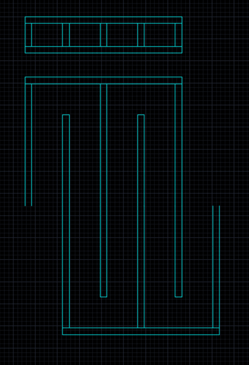
Question for the weldment gurus out there. I have a large welded structure through which flows cooling water in channels formed by baffles. The baffles are formed by welding strips of steel plate to large surface plates exposed to extremely high temperature (if not cooled, the steel plate would likely melt - and it has when cooling has failed).

When failures occur in the structure, it's typically the result of cracking at the base of the welds. I'm new to the project to investigate alternatives, so I haven't been able to observe a failed specimen yet but I have a couple questions until such an opportunity arises. Can anyone point me in the direction of a good resource for thermal strain characteristics of weld fillers? I want to make sure the fabricator is matching not only strength but also ensuring strain compatibility as the temperature changes. Since the temperature is changing, I know I have thermally induced cyclic stresses. Fatigue is a possibility - cycles are slow (1 every 30 minutes at the fastest), and we usually have to repair/replace this every 3 to 4 months. At that rate operating 24hrs/day it would only see 4380 cycles in a quarter of a year. For a fillet welded T-joint I'd be looking at an Fsr of about 26ksi.

Any thoughts/references would be appreciated. Thanks.
 
Replies continue below

Recommended for you

Your structure is undergoing extreme thermal cycles and worse, there is great variation in temperature within short distances. The toe region of welds is the expected location for fatigue cracks to initiate and then propagate into base metal.
I doubt that residual stresses caused by welding play a significant role (if at all) in the development of cracks. You have severe service conditions and the way to mitigate is to make the structure more flexible; i.e., more accommodating of the large strains imposed by differential thermal expansion. I doubt that changing to higher strength steels would buy you much, since the fatigue (I presume it is that) is strain-controlled.


"Everyone is entitled to their own opinions, but they are not entitled to their own facts."
 
Thanks, ironic. Fatigue is where I'm leaning, though I'm not used to checking it in thermally loaded structures. I'm currently reading a NASA paper on "Low Cycle Thermal Fatigue" so hopefully that'll help me work through this.
 
OP said " When failures occur in the structure, it's typically the result of cracking at the base of the welds. .......I haven't been able to observe a failed specimen yet."

Does "base of the weld" mean the "toe of the weld?

I think you will find long rusty cracks that progressed over time, and initiated from ugliness at the weld toes ( which can be much improved by careful mechanical finishing like TIG washing the toe or grinding followed by peening ) or the root of the weld ( requiring a change in process (.

I think you will also find many refernces that will say something like this -
"Numerous investigations have been undertaken on different joint geometries, steels and welding processes.
This work showed that the principle variables influencing the fatigue life of a fillet welded joint were the
geometry of the joint and the applied stress range.

The static strength of the base metal was observed to have little influence on the fatigue strength for the
range of steels used in bridge and building construct. In addition, the type of welding process employed in the manufacturing
of the joint as well as well as the strength of the deposited weld had little influence. They
were observed to only influence the fatigue behavior if they changed the weld profile significantly and/or provided a weld with
different sized defects. "
 
Thanks, Tmoose. The guys who have been working on this issue in the past (I'm still fairly new at this facility) are wicked smart, but they're not well versed in the finer points and the importance of location of failure within the weld isn't immediately obvious to them. That's why all I have to go on so far is "cracking at the base of the welds."

We're investigating methods to better control the temperature fluctuations while also modifying the structural design to improve flexibility and minimize restraint within the weldment. We'll see how it goes.

Thanks everyone for the advice.
 
" baffles are formed by welding strips of steel plate to large surface plates exposed to extremely high temperature ."

Numerically, what is "large" and "long?"

Are you counting on heat transfer from hot large plate into the baffle strips ? I so, I guess you have to weld the strips to the large surface plates 100%.

How thick are the "strips of steel plate " ? Would they be self supporting and sufficiently self aligning if each strip was cut into 10 shorter pieces, then welded individually to the large surface plate?
Maybe a channel would have to be welded to one of each pairs of short strips, spanning the cut, to keep them aligned. Or tongue and groove the 9 cuts to keep them aligned.

If heat transfer to the baffle strips is not required, leave the strips full length, mostly weld one end, and provide a few guides along the baffle to keep things aligned but not restrict thermal expansion in the long direction.
 
Last thermal imaging that was done (immediately after removing the heat source) was about 550[sup]o[/sup]F. That was on the "cold side" - hot side is inaccessible until it's cooled down beyond useful data collection. 3/4" thick plate, about 150 square feet of surface area. Baffles are welded 100% on one side, and plug welded on the other due to accessibility. Baffles are also 3/4" thick. The assembly is split in half, with the baffles cutting back and forth like a mouse's maze.

Best I can tell is no, heat transfer between the outer plate and the baffles was not a design intent. These things are probably paying for the vendor's yacht, vacation house, or both so they haven't been overly forthcoming with information.

One of my thoughts is attempting a cast steel assembly. Using round flow channels with tongue and groove interfaces for the two halves of the casting, that would reduce the number of welds and improve our flow characteristics. It would likely have to be split into a few pieces, but I think something could be worked out. Sound crazy?

 
PhamENG:
You must be boiling one hell of a bunch of water, fairly quickly…, making a lot of steam. And, that is your cooling mechanism, your heat dissipating mechanism. But, of course, the steel pl. and baffles are acting as heat transfer medium/materials, with large differences in temp. levels, movements and strains, and thermal stresses. 150sq.ft. can be 10’x15’ or it can be 5’x30’ and the water is still introduced at one end, and boiled off half way down the length? Why is the pl. so thick at .75”, when all it is the water container and flow director, right? You really need to learn much more about the details of the system, and reveal them to us. I think Tmoose may be on to something in his thinking that the baffle strips should be cut into shorter lengths, even though the bottom pl. must be continuous, and designed to tolerate the thermal movement at its edges and support points. Done properly, this approach might significantly reduce the stress build-up caused by the large temp. difference of the two attached parts, baffles and bot. pl. This type of detailing might reduce the build-up, accumulation, summation and concentration at a weak detail point or weld defect. In fact, you might be better off eliminating the baffles. Why not suspend a piping system, a spray, flooding system, over the full area of the bottom pl.; maybe even larger spray nozzles over hotter areas on the bottom pl. The piping system is not connected to the bot. pl. or water containing pl., its flow pressure and volume can be modulated to match changing bot. pl. temps. as they vary. You might even put a few temp. measuring devices on the bot. pl. to regulate the spray system.
 
dhengr - not quite. Here's a quick sketch. It's fully enclosed, water flows in through pipes and out through pipes with these cooling channels in between. I'm certain that there is boiling going on in there, but that's not really intentional. Heat transfer mechanism is meant to be conduction from the steel outer plates to the water and then for the water to flow out to a discharge/capture/treatment.

Temperature monitoring has been a problem as most RTDs and similar instrumentation usually burns up. I have somebody investigating remote thermal imaging or pyrometer rigs we can use to monitor and correct flow as much as possible. Though it will take significant modifications to the entire system to get there.

Capture_jhktpc.png
 
Is the process happy with the pressure drop of this device ?

Is the system pressurized to 15 psi or more to raise the boiling point ?

What is the nominal velocity of the water ?

What are the entry and exit water temperatures?

Is the device oriented so vapor can rise and will be bled out of the system automatically and continuously during operation ?

Nice fast turbulent water flow in smaller passages generally cools better.

Is one region of the large plate bathed in fire, or, is the heating of the plate fairly uniform?

I think rearranging the baffles so there is a "manifold" at each end, and each baffle forms passages that connects each manifold without wigglng back and forth might help.
Right now each slug of water that enters gets hotter and hotter as it passes over every inch of the hot plate, until it reaches the outlet. IF the plate in the last 1/3 of the travel is as hot as at the beginning, when the slug nears the exit it may be close to plate temperature and incapable of absorbing much more heat.
 
Tmoose - while I play with concepts to improve performance, I've already started working with the O&M team to implement instrumentation to gather the data you're asking about. This thing has been "business as usual" for many many years, and was just considered a "consumable part" for a long time and so no meaningful data collection was attempted. It's only been in the last 6 months or so that somebody decided enough was enough. I'm the first person (internally) to touch it who has had engineering design experience (albeit in building structures, not extreme environment heat exchangers), so I'm trying to get as much data as I can. I'm also meeting with the engineers from a new vendor in the coming weeks to discuss options and brainstorm.

Thank you for the manifold suggestion as well as all of the others. This is probably going to be a months long process - I'll share whatever advancements we make and new data that comes to light.
 
Out of curiosity, is there a good source for coefficients of thermal expansion for weld fillers in service? Or is it better to find a listed base metal with chemistry comparable to the as-deposited filler?
 
"I'm trying to get as much data as I can. "

Excellent.

If it truly is a "consumable part" then failed examples should be readily available.

thanks,

Dan T
 
If similar filler, thermal expansion should be the same. I hope no austenitic filler is used (like a 309), as people tend to do that sometimes...

Thermal stresses come from different expansions due to different temps, don't focus at the expansion coefficient of the filler.
 
Thanks, kingnero. No austenitics here. Trying not to focus on it - just trying to make sure I have a holistic view of what's going on. I appreciate the insight.
 
Actually I got confused with my units - the CTE of weld is approx 7E-6 per deg K (not per deg F). A36 is about 11E-6/K, which interestingly is quite a difference. Though if there was a significant CTE difference and it was a thing, I would have expected to have heard about it.
 
I expect the thermal gradient is so high that the resulting stresses are larger than the material can reasonably take.

The first thing I would look at is the ends of the plates that form the channels with an eye to ending them in a 45 degree or greater slope so the gradient is spread over a longer distance. I would use an FEA model to first determine the expected gradient and then use that as a basis for a strain/stress analysis.

I would also consider not having any channel plates welded directly at all, but it's possible that the gradient through the face plate would cause it to buckle from the gradient through the plate and that corrugating that plate is not an acceptable solution and may not be sufficient to keep a useful shape.

Complicating this is that the properties of the materials are significantly different at the suggested temperature from their room temperature values.

For similar changes in temperature and gradients the solution has been to dovetail the attachments so that normal forces are resisted while limiting shear forces. Without more information I don't know if the geometry would work, but it is how demanding conditions in gas turbines / aircraft turbine engines is handled.
 
Status
Not open for further replies.
Back
Top