Eng-Tips is the largest engineering community on the Internet

Intelligent Work Forums for Engineering Professionals

  • Congratulations waross on being selected by the Eng-Tips community for having the most helpful posts in the forums last week. Way to Go!

Thickness effect in crack-tip stress analysis 1

Status
Not open for further replies.

csmanien

Mechanical
Jan 13, 2010
7
IN
Hi
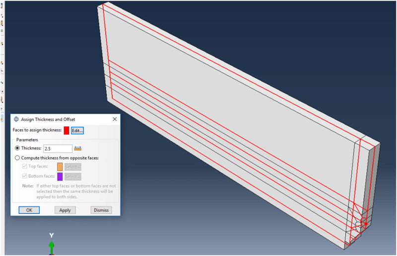
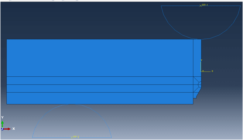
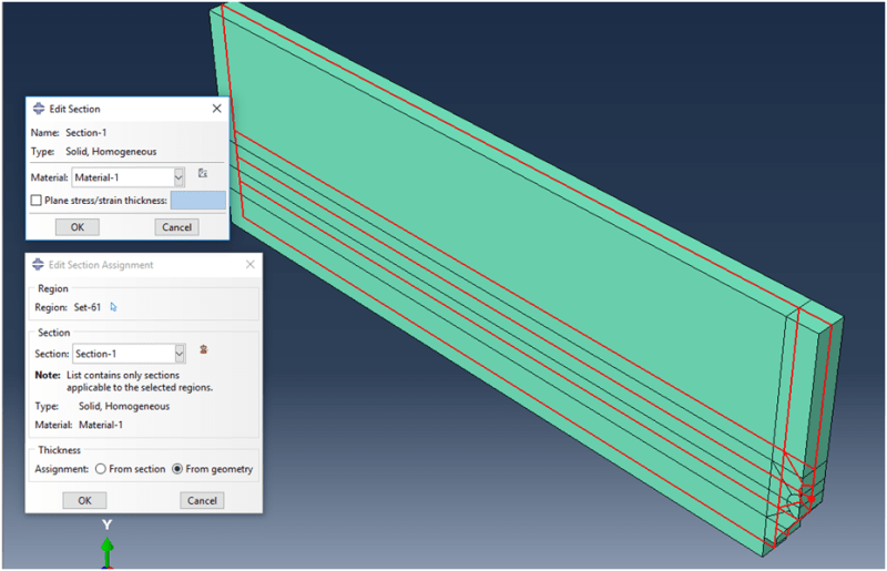
I am analysing crack-tip to study thickness effect in Elastic Plastic fracture mechanics. Here I have taken two TPB specimen geometry with a/w 0.3 and 0.5 with 10mm and 2.5 mm thickness. I have used 'Tool-Midsurface-Assign thickness and offset' option to specify thickness rather than 'using 'Plane stress/strain thickness=' option in section. I have also given thickness 'from geometry' in 'section assignment'. 4 different input files were created. I used CPS8R plane stress element. but in the result, I get the a/w effect in crack-tip stress-strain analysis and not thickness effect (result in both thicknesses are same). I have attached a pdf with the input file of a/w 0.5 with 2.5 thickness for your reference. I suspect, I have committed some error in my abaqus analysis. Kindly help me in this regards.
New_Picture_1_ykmt2n.png

New_Picture_lz9iqf.png

New_Picture_3_i3jsd2.png

 
Replies continue below

Recommended for you

Taking the geometric thickness is only possible for shell elements. You are using 2D solid elements. Enter the plane stress/stain thickness value manually in the solid section menu.
 
Thank you Mustaine3 (Mechanical) for the reply.
I found ,no significant difference in stress when tried with CPE8R with different thicknesses. After your reply, I have changed my analysis to 3D shell planar with S4R elements with different thicknesses, but still I couldn't get the decreasing crack-tip stresses at mid-plane. The section details are given below. Where I am wrong?? whether, my element selection was wrong??? Other parameters are as same before.

*Element, type=S4R

** Section: Section-2
*Shell Section, elset=Set-9, material=Material-1, poisson=0.29
5., 11
 
Shells are not applicable for your situation. As mentioned, run it 2D and define the thickness manually in the solid section.
 
Thank you Mustaine3 (Mechanical) again for the reply.
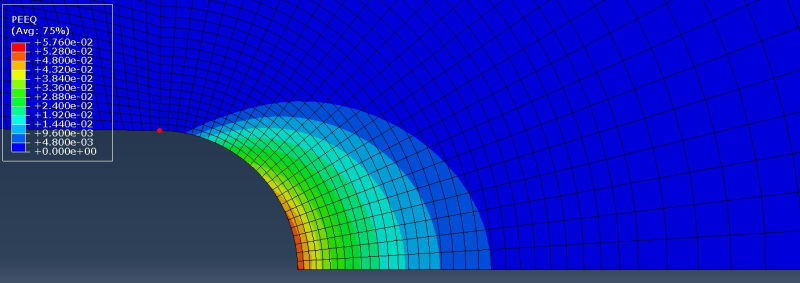
As per your advice, I ran my analysis in 2D solid with CPE8R plane strain analysis on 20,10 and 5 mm thick specimens of a/W0.5. Plane stress/strain thickness in section is also assigned. I expect decreasing S22 at the crack tip (at the same CTOD/CMOD) as thickness decreases, but i got same stress at all the thicknesses. inp files for 10 mm thick is attached herewith. need help please.
New_Picture_coeyi0.jpg

New_Picture_1_qfogvm.jpg
 
Maybe you think again what you are doing and then you try to explain, why you expect the stresses to be different.
 
I am studying the constraint effects in fracture. I took different geometries to evaluate crack-tip constraint parameter 'Q'. The constraint variables consists of geometry of the specimens, a/W ratio, loading modes and B/W ratio. B/W ratio involves thickness effects. The critical fracture toughness increases when thickness of specimens decreases and stress-strain field in crack tip start changing to plane stress state from plane strain state. As thickness of the specimen decreases, tri-axial stresses loss their dominance due to out-of-plane effects at the crack-tip. This becomes two parameter fracture mechanics. lot of literature available on the said topic. I wanted to simulate the crack-tip stress fields (particularly Syy for quantifying 'Q')using abaqus to check all these constraint variables. Though I specify the different thicknesses in Plane Strain or Plane stress analysis, abaqus gives same results neglecting B/W effects. How to get in-plane as well as out-of-plane effects using abaqus if CPE or CPS elements doesn't work for out-of plane effects? IS 3D THE LAST OPTION??
 
Isn't z the thickness direction, so S33 is the variable to look at?
 
I have not paid close attention to this thread so, correct me if I am wrong in my apprehension: Are you even running a fracture mechanics simulation at all? Or, are you simply running a classic hole-in-a-plate toy example?

*********************************************************
Are you new to this forum? If so, please read these FAQs:

 
Thanks for the reply, Mustaine3
- z is the thickness direction.

IceBreakerSours
- I am running a fracture mechanics simulation.
 
Hallo
In my opinion you need to use plain stress elements to model the different specimen thicknesses, and, both material (plasticity) and geometry non-linear effects should be simulated. As the load increases, you must be able to see the stress rising until it reaches the specified yield strength, where after the rise in stress becomes much slower as the material yields locally (relieving peek stress).
Regards
 
After literature search, It is concluded that 3D is the final option for evaluating both in-plane and out-of plane effects at the crack-tip. Thanks Mustaine3 for good discussion.
 
Hallo again, Csmanien.
Yes, to my diffidence, I have to agree about 3D elements being the applicable element type for this purpose. Mislead myself by the thought of having to specify thickness in case of plane stress, and not so for plane strain! By second thought I agree that although the resultant (or sum) of the stress variation throughout the thickness is zero, there will still be a variation to be captured (thinking “shear lips” forming here!). Of course also easier to depict and see the deformation and stress gradients throughout the thickness. Apology and thanks for your response above.
Trust you meanwhile got the results you wanted!
Regards
 
Status
Not open for further replies.

Part and Inventory Search

Sponsor

Back
Top