Continue to Site

Eng-Tips is the largest engineering community on the Internet

Intelligent Work Forums for Engineering Professionals

  • Congratulations KootK on being selected by the Eng-Tips community for having the most helpful posts in the forums last week. Way to Go!

Thought process for creating this shape? 1

Status
Not open for further replies.

_MechEng95

Mechanical
Feb 28, 2017
22
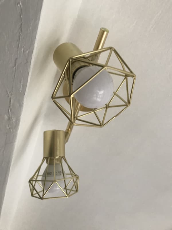
IMG_1737_fbkhy1.jpg


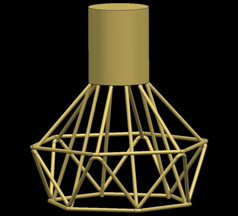
Wanted to produce this 'light shade' ornament thing.

I am a great novice at CAD, my steps to produce this were as follows:
[ul]
[li]Sketch circle[/li]
[li]Offset[/li]
[li]Create Datum/Plane above circle[/li]
[li]Sketch Hexagon[/li]
[li]Offset[/li]
[li]Repeat for Upper Level[/li]
[/ul]

This is where I am stuck as to what the most efficient approach is.

If I extrue I obviously get a solid and would have to create a lot of sketches and subtract areas.

I was looking at using Ruled but this creates a sheet. What would you suggest in order to achieve the wire frame feature?
 
Replies continue below

Recommended for you

this type of questions are tricky, i have difficulties not to try find a reasonable solution...
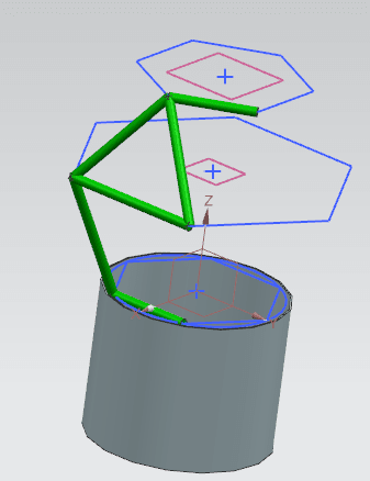
The geoometry is 3 planar hexagons, connected by straight lines.
Three sketches, hexagons, on three planes, 2 of these offset from =0;0;0
Then three lines to connect between the sketches.
Tube features on the three lines + 3 lines from the 3 sketches
Geometry instance, circular of the tube features, n=6, angle = 60

2018-05-30_14-18-38_cqop6u.png


- Simpler solution, anybody ?

Regards,
Tomas


Thanks for the tips,

So I created the three sketches across three planes.

Sketched a curve in 3D space.

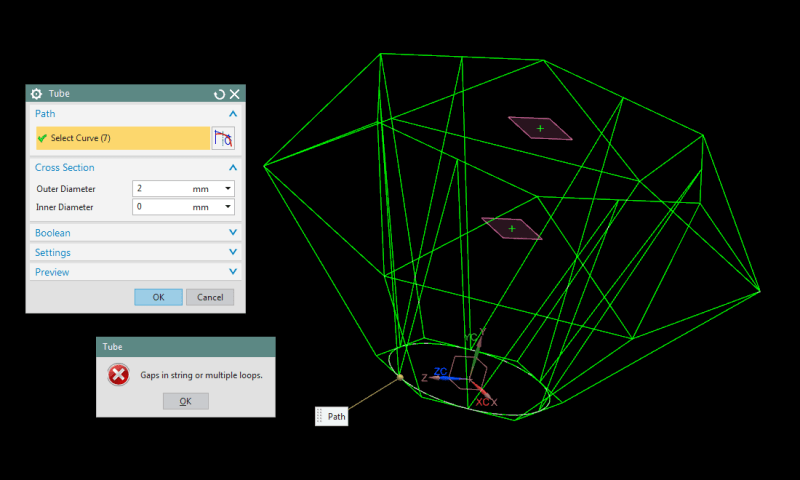
Attempt to use the tube tool, get an error:

Capture_xwjht6.png


Gaps in string, I am stuck.

Any suggestions?

I think I will try sweep along a guide.
 
The tube command does not like sharp corners. You will either need to create them individually (such as in Toost's pic above) or add smooth transitions between the lines that constitute a single wire (as in the original photo, you can see the bends in the wire that goes around the circumference).

www.nxjournaling.com
 
@Dawson70 Thanks for the reply. I cannot open the file (error: this is not a part file). I suspect it is a version issue (Running NX 9.0)

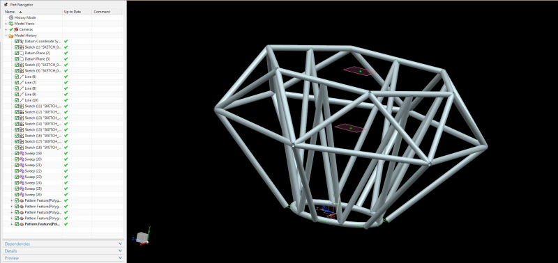
I attempted sweep, it worked well but still ended up with corners being an issue, after patterning I have 1 corner which fell short and did not intersect (faces just touch) then every other corner was too blended and I had no solution to trim the corners in to one.

 
For reference this was the result from sweeping and patterning. The corners do not fully join and I can't figure out how to extend if that's necessary.

Capture_ov7kpp.png
 
I should've attached an iges file instead. Hopefully this will help. It's all freehand using tubes, curves and patterns.

Capture_s8uhsc.jpg
 
@Dawson70 - Thats interesting, 100% of sketches made in 3D space.

So if I understand, 3 planes, 3 3D sketches on them planes, and then smooth curves in space between planes then use tube feature.

I wonder how I would join each corner, optimizing this for 3D printing.
 
Status
Not open for further replies.

Part and Inventory Search

Sponsor