Continue to Site

Eng-Tips is the largest engineering community on the Internet

Intelligent Work Forums for Engineering Professionals

  • Congratulations IDS on being selected by the Eng-Tips community for having the most helpful posts in the forums last week. Way to Go!

Three segment composite tolerance

Status
Not open for further replies.

ASHWA

Automotive
Oct 7, 2020
53
thread1103-468608

Dear All,
Had a doubt in Three segment composite tolerance,
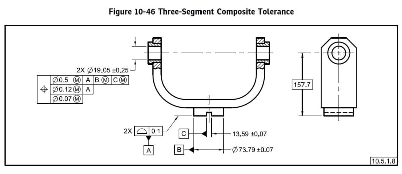
DSSS_xtsmup.jpg


In this,

for B Size limit - (73.72 - 73.86 (MMC))

for C Size limit - (13.52 (MMC) - 13.66)

If my B Size = 73.8 & C = 13.6, which got after machining.

Will there be shift in Hole axis?

SME's kindly resolve my doubt.

Thanks.
 
Replies continue below

Recommended for you

That's actually an interesting figure to discuss.
For the numbers to have any meaning, we would need to make an assumption about the missing perpendicularity control of datum feature B with reference to datum A. Let's suppose that it is zero at MMC. We can make a similar assumption about datum feature C. Then the MMB of datum feature B for the position control is 73.86.
Since datum feature B width came at 0.06 mm smaller than its MMB, 0.06 datum shift is available for the pattern locating tolerance zone framework. This shift can only be utilized for rotation of the two holes about an axis of the datum reference frame perpendicular to datum A. Now regarding datum reference C - since it is not allowed to constrain the rotation which is already constrained by datum reference B, its role is vague. A more interesting question could be asked if it came at a size closer to it's MMC than 73.8 is to 73.86. Let's say 13.54. It could potentially override the datum precedence order. I think the datum references scheme in this figure is flawed.
 
C has a critical and obvious function. What is missing is a geometric tolerance linking it to the other datum features. No surprise the ASME committee continues to promulgate such sloppy work. Whether it's inclusion can override anything depends on missing information. I guess they should have gone ape-sh*t and used the full (X,Y,Z,u,v,w) explicit Customized Datum Reference Frame (unless the committee renamed it in 2018 for no reason.)
 
With both datum features B and C producing a center plane datum, nominally at an identical location and orientation relative to the rest of the part, C as a tertiary datum feature is pretty much useless. It has nothing to contribute to constraints of degrees of freedom or datum reference frame establishment.
It would only make sense if the slot was shown at the right-hand view.
Since the same mistake is in the 2009 version of the standard, apparently the committee had at least 9 years to correct this error but unfortunately, it failed to do so.
 
Datum feature B produces an axis, not a plane.
 
3DDave is correct. I missed the diameter symbol on the size dimension of datum feature B. I was too quick to criticize the committee.

ASHWA, the simple answer to your question is that datum shift will be available IF (edit: one or) both datum features are not produced at their MMB (which is affected by size and orientation for B and size, orientation and location for C). We do not know what their MMB is because the geometrical controls of each datum feature relative to the higher precedence datums are missing. But for the diameter, the MMB is at least as big as the MMC, and for the slot, it is at least as small as the MMC.
 
Thanks, Always Eveready - Burunduk (Mechanical) & 3DDave (Aerospace),


Burunduk (Mechanical),
Does Datum C, influence in Location?

and also with the shift in Datum Axis from MMC of B & Shift in Datum plane MMC from C, Influence a shift in Hole position Perpendicularly. - Is my statement correct?
 
ASHWA,
What I said is that the MMB size of datum feature C is influenced by its assigned positional tolerance (missing in the example) relative to datum references A (as primary) and B (as secondary), hence by its allowed orientation and location error relative to the datum reference frame established from datum plane A and datum axis B.

The shift that may occur between datum feature C and datum feature simulator / true geometric counterpart C may only influence the orientation of the coaxial holes; It may allow some extra rotation about datum axis B.
 
Thanks Burunduk (Mechanical),

Thanks to other SME's too...!!

Happy New Year...!!
 
Also, because datum feature simulator A constrains 2 rotational degrees of freedom (the two available other than the one which is locked by datum feature simulator B), the possible shift between datum feature B and its simulator only influences the location of the two coaxial holes; it may allow some offset between the axes of the holes and datum axis B.
 
Status
Not open for further replies.

Part and Inventory Search

Sponsor