Continue to Site

Eng-Tips is the largest engineering community on the Internet

Intelligent Work Forums for Engineering Professionals

  • Congratulations GregLocock on being selected by the Eng-Tips community for having the most helpful posts in the forums last week. Way to Go!

Throttling capability of Valves with Inching Means

Status
Not open for further replies.

Sawsan311

Chemical
Jun 21, 2019
303
Dear All,

I would like to get your views on the selection of motor actuated ball valve witch inching facility as a throttling valve at pump discharge during start-up. I am doubting its ability to accommodate low Cv values during high pressure drop conditions. Have you experienced any use of such valves. I also understand that ball valves used for throttling tend to cavitate to a great extent in comparison with globe and hence I predict it will experience poor performance.

On the other hand, and if we want to compare ball to globe, which one do you believe is worse when it comes to fast closing and surge impact i.e faster closing time. I believe ball is still wosw.

Appreciate your views.
 
Replies continue below

Recommended for you

Ball valves are poor control valves.

I've never seen inching facility use don a pump discharge.

Officially you shouldn't open ball valves under high DP - tends to rip the seats apart, especially if you have any "soft" elements included. Even metal to metal seats will suffer if you do it too many time.

You can't make statements like ball is worse than globe until you understand the particular pipeline and its issues. Both will open and close at a speed determined by the designer.

Remember - More details = better answers
Also: If you get a response it's polite to respond to it.
 
Sawsan311 said:
Have you experienced any use of such valves.

We have used actuated ball valve with positioner as a "dribble valve" for decades. It is highly accurate, very robust, and inexpensive. When initially fast filling a "weigh tank" or "mix tank" on load cells, dribble valve is 100% open. When weight gets close to desired weight, dribble valve almost closes, to say 5-10% open, slowing the flow significantly. After 1-2 minutes, when tank gets to desired weight - preact amount (for drainage), off the pump and close the dribble valve. With very little tuning at commisssioning, a ball valve dribble valve is very accurate and very repeatable.

Good Luck,
Latexman
 
If this throttling is only short term, say less than a minute or so, and the fluid is nominally non erosive, then I dont see a problem with this plan.
Presume you are contemplating doing this because the pump motor cannot deliver the current required when the pump goes to end of curve if the exit valve were to be full open?
There may be some less awkward ways to resolve this startup problem if you can tell us more about what is downstream of the pump.
 
Thanks all for your replies

With regards to inching gate valve or ball valve in general, can rely on its throttling abilities to accomodate high Delta P. Mr. Littleinch stated that ball valve components can fail under high Delta P. What about gate valve?

referring to what Mr.George stated: '' Presume you are contemplating doing this because the pump motor cannot deliver the current required when the pump goes to end of curve if the exit valve were to be full open?'' are referring to the fact that during start-up a ball valve if cracked open would cause the pump to go to right end of the curve. I think this is a concern in any valve operation even if it is a manual hand control valve except that if it is a globe valve the opening will be more controlled. If we provide inching to the gate valve or ball valve wouldn't serve the purpose
 
If you have a relatively small system, say 1-Inch to 2-Inch piping system, you can get by with a gate valve for throttling.

Once you get into larger systems, the gate valve will not stand up to the operating requirements (will wear out prematurely) and will not be economical (energy wasted) to operate.
 
Instead of inching the exit valve, how about a soft start - startup current draw will be much less.
 
A long time ago we used a special ball valve designed to throttle flow that had kind of triangular opening instead of just a round hole. They seemed to work well but I have never seem them anywhere since. Due to the nature of the hole geometry, the flow path was somewhat restricted when fully open but not as much as you might think. That really makes it just like every other sort of valve though.

Brad Waybright

The more you know, the more you know you don't know.
 
Brad, sounds like a V-Ball to me.

Good Luck,
Latexman
 
Latexman said:
sounds like a V-Ball to me.
Nailed it. I guess they're commonly available. Sounds like a good option for the OP.
This one Link offers full-port flow.
Brad Waybright

The more you know, the more you know you don't know.
 
Thank you Mr.Thebard3 the V port segmented ball valve is quite interesting.

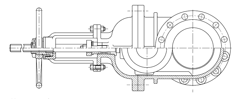
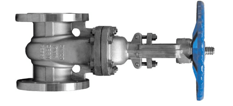
Dear All, I have another small query, with regards to the position of the stem of the gate valve recommended to be in horizontal position specially in flare systems where if the failure of the step would endanger the wedge to fall off down causing blockage of the relief path. My question is, I need to visualize how a valve installed in horizontal plane along a horizontal flare piping would have its stem / plug in horizontal position , is the above statement means that the valve shall be installed in the vertical plane of the piping system i.e. in the pipes descending/sloping downwards such that the stem would be perpendicular and considered in horizontal position and hence it would not fall off the gate causing obstruction?
 
Could be mounted with stem horizontal in a horizontal pipe or stem horizontal in a vertical pipe.

Up to you.

But you need to check with the vendor that it will work properly in that orientation. Not all of them do.

So like this
image_iid4pu.png


or like this

image_zhzdtd.png


Remember - More details = better answers
Also: If you get a response it's polite to respond to it.
 
Thank you so much Mr.LittleInch,

Is the first figure representing a horizontal pipe position.. I am unable to visualize how the stem/spindle in horizontal position can be shown for a valve installed in a horizontally oriented line.

Can you please help?

Thanks
 
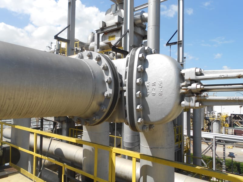
If it is a piping isometric or a P&ID, you may add a note to specify that the valve's stem should be in the horizontal position.

A real application on a PSV discharge line:

DSCN0050_ryianu.jpg


Daniel
Rio de Janeiro - Brazil
 
Yes, but Daniels photo is much better - I couldn't find one on line or in my collection so just chose a drawing.

But you really need to get the valve suppliers buy in as it is not normal to do this and sometimes the valve might need some extra guides or it might be harder to close.


Remember - More details = better answers
Also: If you get a response it's polite to respond to it.
 
Status
Not open for further replies.

Part and Inventory Search

Sponsor