Eng-Tips is the largest engineering community on the Internet

Intelligent Work Forums for Engineering Professionals

Thrust block for water pipe hanging from the bridge structure 3

Status
Not open for further replies.

m1208

Structural
Apr 6, 2011
67
0
0
US
I have a new 14" (ID) ductile iron potable water pipe hanging from the bridge structure. The pipe is approximately 600' long, relatively horizontal, working water pressure is 100 psi, 1500 gpm (max). The pipe will be installed in the snow country. I need to design thrust block for the pipe line. The thrust block system will be steel structural members that brace the pipe to the bridge structure. I see formula for the thrust block design for buried pipe but nothing on the pipe hanging from the bridge. Questions:
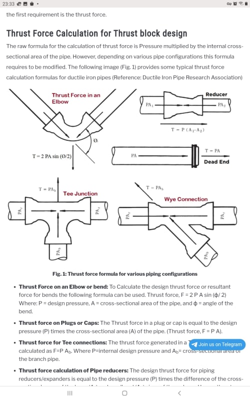
1. Can I still use the T = 2 P A (sin Q/2) equation to calculate the thrust force?
2. Is the Area of the pipe, inside or outside diameter of the pipe?
3. Is the water pressure A, actual working water pressure inside of the pipe (that is active 24 hours a day), or is it the pressure rating of the pipe material (350 psi), which is more than three times the actual working water pressure of 100 psi?
4. Any factor of safety I should consider for the thrust force calculations?
Thanks
 
 https://files.engineering.com/getfile.aspx?folder=fa71a919-300b-4b7c-8383-1a495b4b038a&file=Bridge_Page-3.jpg
Replies continue below

Recommended for you

You can display pictures and drawings using the camera "Image"icon.

Bridge_Page-3_dybzqz.jpg


Looks like straight pipe there. If you have 90° elbows at the ends of this, then yes, that's the formula. If not, where are you putting the blocks? But not sure how you will handle thermal expansion/contraction of the pipe between two thrust blocks.

Screenshot_20240124-233329_Brave_sogrby.jpg


--Einstein gave the same test to students every year. When asked why he would do something like that, "Because the answers had changed."
 
And I've only seen rollers like that on cryo pipe where it moves inches at the end points....

Remember - More details = better answers
Also: If you get a response it's polite to respond to it.
 
Thanks for the info. Yes the pipe has 45 and 90 turns. I will use the same equation but with some questions:
1. Is the Area of the pipe, inside or outside diameter of the pipe?
3. Is the water pressure A in the formula, actual working water pressure inside of the pipe?
4. Any factor of safety I should use?
 
1. The pipe itself isn't flowing, so it's the area of the water flowing in the pipe - so inside

3. The design pressure would be the max pressure that can be expected in the pipe
 
It is typically called the "design" pressure. That may be much higher than normal, especially if there are waterhammer issues. Large elevation differences can also cause normal pressure at one point to be much higher, or lower at one point or another. Use "design pressure". That will include whatever safety factor the design engineer determined would be needed.

--Einstein gave the same test to students every year. When asked why he would do something like that, "Because the answers had changed."
 

1. Is the Area of the pipe, inside or outside diameter of the pipe?
A= External diameter of the pipe. Consider the socket joints.The gross pipe area ( A) subjected to pressure .
3. Is the water pressure A in the formula, actual working water pressure inside of the pipe?
A= Water pressure (P) in the formula, test pressure inside of the pipe.
4. Any factor of safety I should use?
A= In past , i have used min. F.S.=2.0 . This must be decided with OHJ , client ..

Good luck.

Use it up, wear it out;
Make it do, or do without.

NEW ENGLAND MAXIM


For bridges in NYC that carry water mains, the practice is to use a thrust plate anchored to one backwall. We use the operating pressure and inside diameter in our calculations.
 
Status
Not open for further replies.
Back
Top