Eng-Tips is the largest engineering community on the Internet

Intelligent Work Forums for Engineering Professionals

Timber balustrade connection

Status
Not open for further replies.

kauri

Structural
Aug 13, 2018
36
0
0
GB
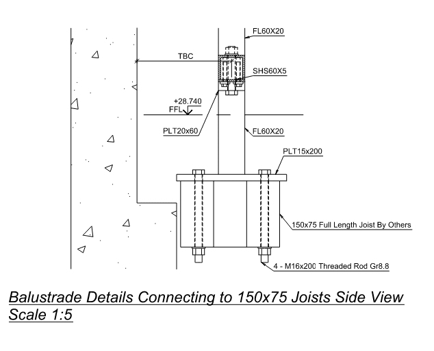
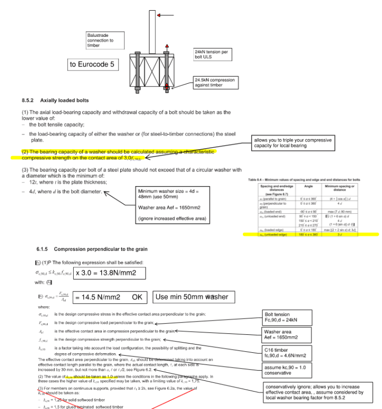
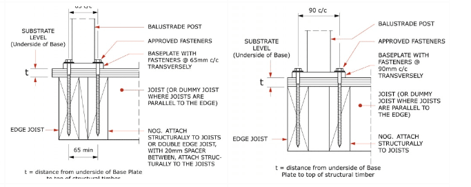
How do you rationalise these types of balustrade connections?

Screenshot_2024-09-03_160105_whnyi0.png

Source:
Withdrawal strength wouldn't be an issue, but I thought you need 5d edge distance for shear.
How about torsion - is this nominal and taken out by joist end connections and nominal stiffness provided by the dummy joist?

Cheers,
Kauri
 
Replies continue below

Recommended for you

Hah, I've been looking at their details too recently as we got asked to do the engineering for a steel balustrade supplier
I came to the conclusion that balustrade fixings are a very dark art that dubiously calcs out

I suspect their argument for shear is that the back fixing could take it all and put it into the floor so the joist is only for uplift
Or maybe they just ignored the shear. Who knows

Balustrade engineers always tag out the substrate (as we did on our drawing set) to be designed by Others to take out the torsion
NZS3604 contains some standard balustrade substate details (Figure 7.10a) or you can use the Mitek one
So, there has to be a system beyond what is shown in that detail but the specifics of the system will vary according to the situation
 
I would not worry about shear as the friction from the compression portion of the couple should resist it.
Also, getting those fasteners centered in the wood is wishful thinking at best.
 
Are there 4 screws attaching the base? (Sorry, the website linked isn't working for me.)

I'm based in the U.S., so I'm not familiar with the applicable building code in your case, but I'll just assume it's similar to mine. Based on that assumption, with a 200 lb force applied at the top of the post, located 36" above the deck, and assuming the fasteners are spaced 65 mm apart (roughly 2.5"), that results in a very large tension/uplift force of 2,880 lbs and the same compression force. Assuming 2 screws are in tension, that's 1,440 lbs each. Your shear force of 200 lbs is rather insignificant here. The tension and compression forces, however, are not. I wouldn't automatically assume the screws are adequate in withdrawal, especially if this is an exterior deck which gets wet.

Besides that, a 2,880 lb point load on the joist isn't insignificant, nor is the potential for perpendicular to grain crushing on the compression side.

Perhaps this can work, but it seems a bit questionable. I'd like to see some actual calcs justifying it, if they exist.
 
@Eng, I'm in his same jurisdiction and have done similar calcs a couple of months ago
Typically these baseplates have 4 screws in them, though not always
I'm pretty sure this particular detail does have 4 screws, from my memory of looking at it

The tension forces are pretty brutal but can be made to work in a 190 member - it's on the line for a 140 member
 
Greenalleycat said:
The tension forces are pretty brutal but can be made to work in a 190 member - it's on the line for a 140 member
I'm not in the metric world (unfortunately), but I assume those values refer to the joist depth and therefore the maximum embedment depth of the screws. Interestingly, if that's the case, that's roughly what I was coming up with in terms of required thread length for withdrawal. Technically, I wasn't quite getting it to work with a 190 member, but it was close. Of course, this was based on several assumptions concerning the particular screw and lumber type. Seems like we're both roughly on the same page.

I'd like to test one of these connections in the real world. Seems like any significant force would crush the wood and the post would move a fair amount. Perhaps that's no different than many of the other common details though.
 
Yep you've got it correct - 140mm or 190mm joist
Off the top of my head, our balustrade calced out as requiring 130mm embedment I think, some on the line for 140mm joist

Yes I also wonder about these things
I think balustrades sit in an awkward world where every few years there is a dramatic failure of a balustrade/deck that causes people to be very scared of them
But it's usually some old, rotten, non-designed crappy thing that doesn't really match what is done in modern construction
But it's scary enough that it gets everyone alarmed so we design for these huge theoretical loads that don't seem realistic
 
Hi guys, cheers for the responses,
I am in agreement with @Greenalleycat, balustrades are truly a black magic!

My contractor's engineer keeps showing this nasty connection, but refuses to provide any calcs; "timber by others". Certainly their connection doesn't work, because they've forgotten to provide a washer...
balustrade_detail_tipvvs.png


I went down the rabbit hole anyway, more out of curiosity than anything. These are 4-bolt baseplates @ 720 crs, with a 1.5kN/m live load 1.8m high. I am operating in the UK and ran this calc to EC5, looking at compression in the washer. It looks wrong, but because the EC allows you to triple your compression strength with a washer, this connection barely just works.
Shear is ignored - with a 1.5kN/m line load this works out to a negligible 0.4kN per bolt. Maybe need to look at 1.5kN point load, eh.

balustrade_calc_rukmu8.png


Coach screws I can't figure out - while you can just get enough withdrawal strength, you'll never meet minimum edge distance requirements for axially loaded screws (given in EC5, can't find in NZS3603?) - and I believe then you need to reduce your capacities. I think they are only suitable when spaced at close centres.
 
I'm not saying it necessarily meets code, but I think I like the bolted connection better. It definitely needs a decent sized plate washer, though, like you noted.
 
Status
Not open for further replies.
Back
Top