Continue to Site

Eng-Tips is the largest engineering community on the Internet

Intelligent Work Forums for Engineering Professionals

  • Congratulations cowski on being selected by the Eng-Tips community for having the most helpful posts in the forums last week. Way to Go!

Timber beam and steel column connection

Status
Not open for further replies.

Aleeeex

Civil/Environmental
Aug 14, 2020
42
Hi guys,

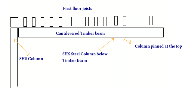
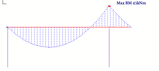
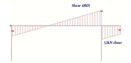
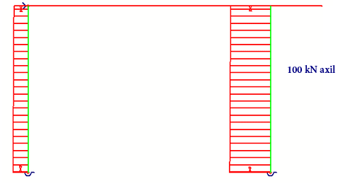
I am working on a small project of extending a home. The extension consists of steel columns and timber beams which is uncommon to me. One issue is the timber beam will span over a steel column using a column cap plate and it will be cantilevering for 1 meter. You can see my analysis below.

The column cap plate is 12mm and it will be welded all around to column and bolted to the beam with 4no. M16 bolts.

Can anyone explain how to check the connection?

In terms of Column's cap plate capacity. If there is any worked example.


Your input is much appreciated.


image_y9lrkq.png


image_vbcob5.png


image_j1bdl4.png


image_zayuyc.png


image_ia8fln.png
 
Replies continue below

Recommended for you

If there's no uplift, then there really isn't much to check at that connection. Less bolts is better to preclude splitting of the lumber when it shrinks. I'd be looking at only 2 bolts, no higher than D/3 (beam depth) to avoid potential splitting issues. As you currently have detailed, there's a high likelihood that the wood will shrink enough between the upper bolts and the column that the wood will split at the upper bolt location.

You can have your side plates extend up past the halfway point if you'd like to have some resistance to the beam rolling over in the saddle, but I wouldn't put bolts that close to the top.

If there is uplift, then that's a whole different can of worms.
 
Don't forget to check compression perp. to grain.
 
Thank you Jayrod

In my first case there was no uplift, however I am using the same connection in a different location I got 32kN uplift.

Please advise


I've done lots of these with a single bolt near the bottom, and a seated connection... I also like using glulam 'rivets' for connections...

Rather than think climate change and the corona virus as science, think of it as the wrath of God. Feel any better?

-Dik
 
I think I'd be more concerned about the connection at the left hand column. The shear is lower, but it has to be carried entirely by the connection. Why not let the beam run over the LH column?

BA
 
You could check the bearing stress perpendicular to grain for the wood at the beam support. See below.

bearing_stress_perp_to_grain_check_kqakgx.png


For the bolts you'll need to check their capacity for the uplift load. You can get double shear design reference values for load perpendicular to grain in the main member. I think the table below would be the one you'll need from NDS 2018. But you'll have to use the correct adjustment factors to modify these reference values based on your bolt spacing and edge distance.

table_12G_bncrl9.png
 
For uplift you need to check for the appropriate loading direction on the bolts, and make sure you meet the minimum spacing requirements to engage the number of bolts you need. The failure mode in that case is splitting perpendicular to grain. 32 kN is quite a bit. You may need to strap over the top of the beam if it turns out you need a signficant number of bolts to make the uplift work.

And for the lefthand column, I'd be welding a bearing shoe onto the side of the column. Easy and clean.
 
Status
Not open for further replies.

Part and Inventory Search

Sponsor