Continue to Site

Eng-Tips is the largest engineering community on the Internet

Intelligent Work Forums for Engineering Professionals

  • Congratulations KootK on being selected by the Eng-Tips community for having the most helpful posts in the forums last week. Way to Go!

Timber diaphragm discontinuity 2

Status
Not open for further replies.

Uzs1

Structural
Jul 3, 2022
12
Hi fellows,

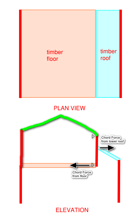
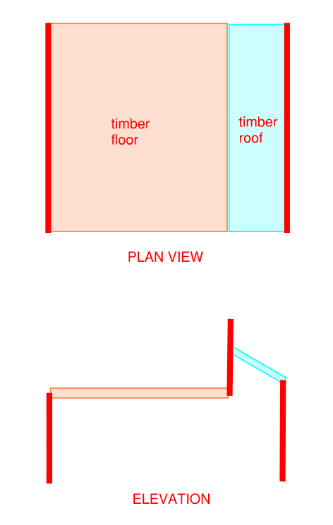
I have a situation where the timber floor is disrupted by another roof at different height, and I cannot employee any internal lateral resisting system due to the limitation of the layout. It seems like the only way is to use external walls for lateral only, which means the diaphragm has to be continuous. I am wondering what you would do and what the analytical mode would be?
2022-08-04_133527_vm55hk.png
 
Replies continue below

Recommended for you

The red lines are timber stud walls
 
I generally don't worry about issues like this in residential although I am in a low seismic/wind area. Most houses I engineer have some sort of similar discontinuity.
 
The wall between the floor and shed roof has to be a shear wall. I'm assuming it is anyway, since it has to bring the load down from a roof above that. Instead of having a load applied at the top and resisted at the bottom, it'll have a load applied at the top (from the roof not shown), a load at the bottom (from the floor that is shown), and those will be resisted in the middle where the shed roof ties in. The shed roof is then a three sided diaphragm with a load applied along the edge where connects to the 'floating' shear wall. Of course there's a bunch of vertical reactions here you'll have to deal with.
 
phamENG said:
The shed roof is then a three sided diaphragm with a load applied along the edge where connects to the 'floating' shear wall.

Hard to be certain from the limited drawings, but if the structure is scaled anything like the drawings show, I'm betting you are going to have aspect ratio limits to deal with, which may not be easily resolved.

I would personally treat the 'timber floor' as the 3-sided diaphragm, and take the lateral loads from the shed roof and from the roof above the second floor, and carry them through the timber floor diaphragm over to the shear walls on the left side of the structure, and resolve the loads that way.

Edit: Made second paragraph easier to understand.
 
You will need a beam to support that middle wall. Just make that beam and column (I am sure you need more than 2 columns) as moment frames.
 
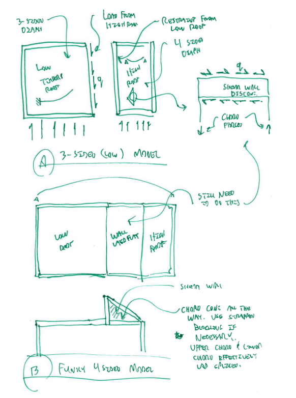
1) The first sketch below shows the version of the 3-sided diaphragm story that I would tell. I think that it matches Choras's model and only has aspect ratio problems if the left side has aspect limit ratio problems as a three sided diaphragm.

2) The second sketch below shows a non-3-sided diaphragm story that I think one could tell if:

a) The low roof chords could extend the full width of the building and;

b) The wall connecting the low roof to the high can be a discontinuous shear wall in it's own right.

I'm guessing that it is this second model, or something like it, that justifies XR250's lack of concern.

C01_nx9xyn.png
 
Thank you very much.

Sorry for the wording. Yes, there is one roof above, see below image.
I will go ahead with the 3-sided diaphragm approach. However, I was wondering if we can treat the floor and lower roof as one single diaphragm using the wall above? Please see below.

2022-08-04_133527_oyfrgf.png


@DoubleStud, I do need a beam under the middle wall but it is going to connect to beams instead of columns due to openings. And even if the ends are columns, they will be limited to 90mm square hollow sections only, which doesn't provide much lateral resisting capacity anyway.

@KootK, Thank you very much for the explanation in sketch! I don't think the bottom chord in your second sketch is allowed for this job though. Because the lower roof will be rafters instead of trusses.
 
Status
Not open for further replies.

Part and Inventory Search

Sponsor