Eng-Tips is the largest engineering community on the Internet

Intelligent Work Forums for Engineering Professionals

Timber Framed Cider Press Design. How to strengthen the press beams.

Status
Not open for further replies.

Weaverofduart

Agricultural
Nov 5, 2010
28
0
0
AU
Hi Peoples,

Now I'm finally getting around to a project that has been on my to do list for ages.

We have been making cider from wild apples for about the last 6 years. As much as 500L per year.

Processing the apples is a huge job so eventually I made a scratter to speed the milling process. That worked so well. We can now mill 1.5t of apples per hour. Problem though is that the 35L press we have been using is now way too small.

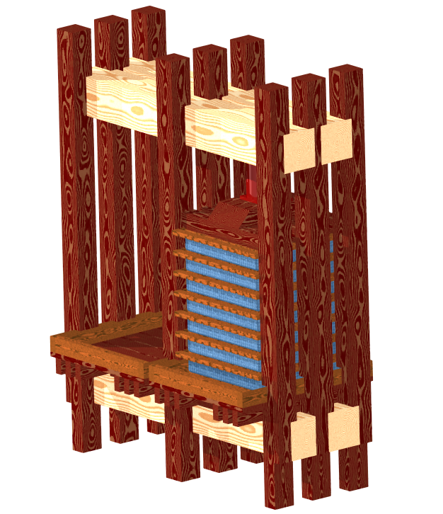
So the plan is to build a much larger press of around 350L capacity. Actually a double press with each side capable of ~350L per pressing.

press_fgpm5o.png


I'm doing a bunch of videos to document the fun which you can find on you tube. There are now 4 in the series but possibly the best one to start you on is where I introduce some of my tool collection. Specifically a bunch of old French and German carpentry tools.

Link

I've got the beams ready to cut and start on the joinery and I've prepared 7 of the 9 posts. So I'm going back and rechecking my engineering in preparation to starting the joinery.

Thats where I've hit a snag.

I've got four timbers that I'll be using for the top and bottom press beams, two at the top two at the bottom.

For the sake of the disscussion lets say these are 10"x10" ea.

I want the press to be able to develop 20t of force to generate 50psi in the press cheese stack which will be ~29" by 29".

P=44,000lbs
A=LxB= 29" x 29" = 841 square inches

S=F/A=44000/841
= 52psi

Horizontal shear in the Beams

V=vertical shear=P/2=22000
A=10 x 10 + 10 x 10 = 200" square

H=3V/2A=3 x 22000 / 2 / 200 = 165psi

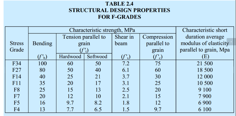
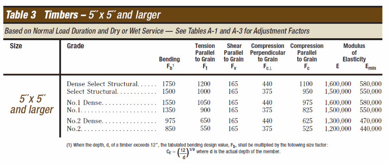
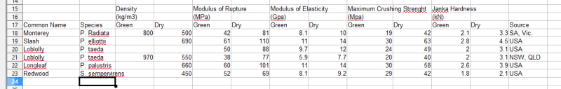
There is the problem. The beams are Monterey pine (P. radiata). The figure I have based on the F grades is that the value for shear in beams for F7 timber is 2.1 MPA or ~300psi.
F_Grade_Properties_xyr9cz.png


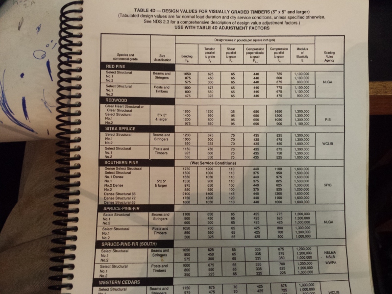
This is WAY above the values given in the timber framing guilds book "Timber Frame Joinery and Design Workbook". There even the strongest timbers tend to be rated way less than this. The strongest is Southern Pine Denser Structural 86 at 145PSI.
20170305_092342_w42p2e.jpg


So how can I modify these timbers to strengthen them. Vertical steel bolts to increase the resistance to shear? Would adding metal strapping to the tension side of the beams help or would that just increase ability to resist bending but do nothing for shear?
 
Replies continue below

Recommended for you

I would start with a 20 ton press from Harbor Freight, which you can buy right now for $170. But I'm an engineer not a carpenter.
In addition you can simply replace the manual hydraulic with an air-powered hydraulic for about another $100. This will allow you to use an air pressure regulator to select how much tonnage to which you wish to squeeze, and the operator can walk away.
 
There used to be a provision in the code that if there were no horizontal checks in the members, the sllowable shear stress could be doubled. Since the shear values were doubled, I have not checked to see if that provision is still there.

Mike McCann, PE, SE (WA)


Weaverofduart - I believe this is what msquared48 has mentioned. The shear values published in "Timber Frame Joinery and Design Workbook" are outdated. A check of the internet indicates that book was published in 1996.

About the year 2000, an error in shear value calculations was discovered. This error has effected published shear values for decades. Here is the NDS explanation and source document for this excerpt.

NDS_2001_Changes_-_Shear_jnpgpt.png


Allowable shear value for southern pine is now 165 psi (see below). If press operational loading is short (say <10 minutes), multiply 165 psi by the 1.6 load duration factor.

SP_Properties-Shear_cpljar.png


Here is this source document.

Perhaps the 300 psi shear value for Monterey Pine is from a newer publcation (post 2001).


[idea]
[r2d2]
 
That is awesome help.

So what is the species for southern pine? Monterey pine is one of the most widely cultivated plantation species but getting information on it for large section timber framing applications is......challenging.
 
Southern pine is a group of related yellow pine species commercially grown in the southeastern USA. The most common are Shortleaf, Slash, and Loblolly. The best is Longleaf, but it was over-harvested in the 19[sup]th[/sup] and early 20[sup]th[/sup] century and is still recovering - it is not available, unless recovered for reuse from existing structures. SYP is a big business and has it's own independent rating bureau.

[idea]
[r2d2]
 
Check also the compression perpendicular to grain at the let-in connection notches. May get some crushing in the sides of the cross beams.
 
Yes I can but I'm trying to keep it looking like a traditional press.

Having said that using steel to "repair" timber structures is a traditional practice.
 
Sister the timbers vertically and use two instead of just one?

Use vertical through bolts with appropriately sized washers/plates on both sides to ensure you're getting good composite action.
 
The tensile strength of the posts is more than adequate for the job so vertical bolts are not need for that reason.

However vertical bolts would help reduce the shear on the joints. The thing is vertical bolts are kind of hard to make look traditional or hide.

According my calcs there is enough relish in the top and bottom of the posts to resist the load. Safe shear stress for redwood posts is given as 0.66MPa. With four shear planes (per side) of 150 x 330mm shear is 0.5MPa so should be safe.

However adding screws of bolts through the posts perpendicular to the beams should reinforce the relish of the joint if I need to.
 
I wasn't talking about the posts, I was talking about the horizontal beams.

Use two instead of one, stacked vertically with the longest axis of the cross section parallel to the posts (if they aren't square), with vertical through bolts tying them together. If you want the hide the through bolts, put the heads of the bolts on the bottom (I'm assuming this contraption is tall enough that nuts/washers/extra bolt length will not be visible on the top) and counterbore the holes a little to hide the heads. If you want to go all out, counterbore the holes a little more and plug them.

The additional beam doesn't necessarily have to be the same size as the original, but the larger it is obviously the bigger the benefit will be.
The other benefit you'll get is based on deflection- if you're stressing the beams close to their stress limits, they will also be deflecting quite a bit. If you sister them, you will get much less deflection for the same amount of press force.

See attached edit of your photo.

Blue: sistered horizontal beams

Red: additional post length to accommodate taller dado for beam fitting (shown on only one post for clarity but applies to all of them)

Green: vertical bolts through horizontal beams to develop good composite action of the beams

Orange: see below

Also- when you're calculating the tensile strength of your posts, have you accounted for the fact that You're not using the whole cross section in tension? The dados you have cut at the bottom of the posts to accommodate the beams are removing significant portions of the post from the load path, depending on how exactly those connections are made.

The area highlighted in orange shows the part of the post that will not see direct tension- any force going into this part of the post is getting there only through internal shear force developed inside the post. This post will be weaker than a post without any dados in it would be.
 
 http://files.engineering.com/getfile.aspx?folder=fb210f89-a385-4de6-9b7f-089ba828fc81&file=press_fgpm5ob.png
Thanks for the time you have taken to respond.

Dealing with last first. Yes I have accounted for the dados. The cross sectional area of the posts required to resist the tension forces in the posts is ~9000mm2 per side. The posts are 150mm x 150mm with 65mm x 150mmm dados. That leaves a cross section of 85 x 150mm or ~12,000mm2. There are three posts per side. So the ability of the remaining posts cross section to resist the tension forces is not the weak point.

Intuitively the point I'm worried about is the relish of the dado but the engineering calcs show I'm ok with shear force in the dados calculated to be 0.45MPa where the safe value for shear for Redwood is given as 0.66MPa.

Intuitively I'm not worried about the beams because they are so huge but......

I've calculated the horizontal shear to be 1.29MPa. The Timber Framing Guilds workbook doesn't provide values for Radiata pine but if I use the updated figures for southern pine (a dodgy practice given its a different species and all) given above a safe value is 1.14MPa. Its only by going to the F-Grade tables that i find safe values that are large enough to pass the beams through the engineering.

Searching for less conservative safe values is not exactly a safe conservative risk free path.

 
Weaverofduart:
I wonder if you aren’t trying way too hard to come up with some grand timber framing project, at the expense of good, clean design with today’s standards and materials. If you really mean traditional press, then it is a single 3T jack or hand screw, four legs, some corsssbeams, etc. If you want to do some timber framing, go for it, but I am not sure that your first concern should be allowable shear stress at the moment. That may well become an issue, but with what little you have shown and explained, I’m not sure we (or you) even know that you have picked the worst stress location at this point. Where is that max. shear on your sketch-up view of your press frame? None of the total loads you are thinking of are going to be simply divided by six joints or six posts, or two beams, for a design load. Your structural system and joinery is much more complicated than that. The three center posts in the long direction are double notched, and more highly loaded than the outer posts; and the middle post of those three center posts is still more highly loaded than the two end posts in that line.

While the joinery seems fairly simple and straight forward, the actual structural framing system is fairly complicated because of this layout, fit-up and joinery, etc. Can both sides (both smaller presses) be operated at the same time, or are they loaded and operated alternately, so that one side at a time has the 10T or 20T press load? With the framing arrangement that you show, the middle columns/posts are going to be very highly loaded, and the middle beam reaction area is going to be highly loaded. There may not be much advantage to having the press beams being continuous over their middle support notches, depending upon how you operate the press. The post notches will be fairly highly loaded in shear and compression parallel to the grain, while the beams will highly loaded in compression perpendicular to the grain at their notched bearings.

I think you would be better off using appropriately sized cross beams 3 above and 3 below the four main spanning beams. These cross beams are at the same support notches locations, on those lines across the frame. These would be held together with steel tension rods which do the primary pressing load work. The steel rods are threaded t&b, with large washer plates on the wood, maybe different sizes. They can be adjusted in length to square-up the frame and level the main beams. Then some simpler compression framing holds the main spanning beams apart when there is no press load, and this framing keeps the whole system from racking, etc. The entire frame would stand on the ground on the 3 bottom cross beams, just as your posts stand on the ground in your sketch. The inner parts of the pressing system would be the same as your sketch shows.
 
To be frank and blunt I'm not interested in good clean design using todays methods. It is as you have said a "grand timber framing project". But one that I don't want to break. Hence the effort on the engineering.

To help answer some of your questions. The two sides of the press are loaded alternately. The idea being one side is pressing while the other side is being cleaned out and reloaded. It takes time for the juice to be forced out of the cheeses and recovery efficiencies relative to load are much higher if you give the cheese stack time to compress and over that time maintain the pressure by regularly operating the jack or screw.

The twin paired beam design serves two functions one it means that I don't have to use a single massive beam but also allows for the beam to also include the nut of a screw press. A traditional practice with such nuts is that they be shaped in two parts which are then bound together to form the nut. The design of the screw and the nut is another issue and will require a sister beam arrangement like what jgKRI suggested to get enough baring area in the screw to prevent the threads shearing and not compromising the structural integrity of the press beams.

I understand there may not be much of an advantage to having the beams continuous over the center posts but would this be a disadvantage?

Your design suggestions in the last paragraph of your post would indeed provide a superior design that would also be easier to construct. However, that design would be a move away from the "grand timber framing project" which is one of the primary specifications of this project.

Consider this similar to an architectural project where the architect wants a specific aesthetic look which requires us to design an engineering solution that is not ideal let alone best practice.

I'm sure you have all had clients and projects like that :) I know I have even as an agricultural engineer.

Also if the primary aim was to recover apple juice from the pomace (apple pulp) then I would just buy an automated belt or screw press.

 
WRT to the top beams being continuous:

There is no (or little) advantage with regard to overall load sharing, because the posts at the far end won't share any (or very little) of the tensile load placed on the center posts and posts on the operating end- although there maybe be a little load sharing, depending on how elastic the posts are. If the center posts have some elasticity under tension, as they stretch the far end posts might attract a little load.

You possibly/probably already knew this, but personally I'm not a wood-under-tension expert so I don't know what level of elasticity in tension would be reasonable to expect from the posts and thus can't estimate how much load the non-operating side posts will attract.

However, if you look at just one side of the machine, there is an advantage to continuous beams. If the beams were not continuous, you would need a joint somewhere, and the most logical place for that joint to go would be on the machine centerline, which is also the centerline of the center posts. Were you to put a joint there, you would be cutting the bearing area that the beam applies to the post dado in half (assuming a butt joint with no glue or fasteners of any kind which would not transmit any shear between sections of the non-continuous beam). This obviously would not be very good for the stress distribution in the posts.

You could put the joint in the same place but attempt to design it to transfer shear- but by doing so you're either relying on an end grain/end grain glued joint (which is not a great plan) or you're going to need mechanical fasteners; it would be difficult to design this joint using bolts/screws in a way that would transfer enough shear to matter, be easy to assemble, and suit the look you're going for.

In short, I see no disadvantage to the beams being continuous- in fact it's better if they are. The only negatives would be buying and handling the larger pieces of lumber, and from your discussion up to this point it seems you're comfortable with that aspect.
 
Any "metal" design can look "classic" with a little attention to details.
Black, heavy, glopped on paint.
Square nut and bolt heads, deliberately "heavy" with big washers. And plenty of that black paint.
Heavy (1/4 or thicker) flat plates. Best if the black painted flat plates are on a dark, heavy-stained wood.
NEVER I-beams, but use riveted angle iron on both sides of a flat web to date your piece to the 1830-1890 time frame.
No welds until the mid-1940's.
Coarse, hand-sawn beams.
Simple flat or single-plane bent steel pieces that could be made by hand (before 1830) or steam forge (after 1830-1840.)
No cold-rolled steel rods or bars - they look too "new", hot forged round and flat stock is available commercially from the ornamental iron shops and on-line catalogs that cater to the stairway, fences, and handrail and gate fabrication communities.
 
Status
Not open for further replies.
Back
Top