Continue to Site

Eng-Tips is the largest engineering community on the Internet

Intelligent Work Forums for Engineering Professionals

  • Congratulations KootK on being selected by the Eng-Tips community for having the most helpful posts in the forums last week. Way to Go!

Timber pile cap details 1

Status
Not open for further replies.

MIKE_311

Structural
Feb 15, 2020
108
I have a timber pile and cap foundation for a small pedestrian bridge I need to design.

I'm envisioning supports like this:


I'm looking for help with details to connect the cap to the piles. I can work out the design, just not sure how this would typically be connected.

Thanks!
 
Replies continue below

Recommended for you

Are you proposing a concrete cap? The piles would extend 6” into the concrete. Sometimes hooks are put into the piles. I have a detail somewhere, need to look through files tomorrow.
 

You could design something like this. If uplift loads are small or negligible and all you need is positive connection, you might even consider drilling and epoxying some stainless steel or GFRP dowels into the top of the wood pile to create a doweled connection. I've been able to get some testing results from Simpson rep for adhesive pullout values in wood.
 
For a timber cap, most of the original installations have a large steel pin embedded in the top of the pile matched up with a hole drilled in the cap.

Where we've had to replace a timber cap, we added steel plates on the sides of the cap and piles, bolted through the cap and pile.

Rod Smith, P.E., The artist formerly known as HotRod10
 
The plan is for a timber beam to be set on timber piles. I'm not familiar with the connection detail from the pile to the cap beam, similar to what's in these pictures:


Is it just an anchor drilled through the cap beam into the piles? It seems pretty straightforward, I just can't seem to find any details of how this connection is typically made.
 
Mike 311 said:
Is it just an anchor drilled through the cap beam into the piles? It seems pretty straightforward, I just can't seem to find any details of how this connection is typically made.

1) Drill a vertical hole, same diameter as the bolt/pin, through the timber cap directly above the center of each pile.

2) Using a sledgehammer, a (strong) worker drives the pin through the cap an into the pile. Want to get at least 12" of the pin embedded in the pile. Top of the pin is at the top of the cap. Use a hot-dip galvanized bolt or dowel. Traditionally, use half inch diameter pin for "small" piling; say, three quarters inch diameter pin for "large" piles. No need to put a point on the bolt/pin, a blunt "nail" cuts it's way through wood just fine and reduces chances of splitting the wood.

Noticed that the plan you posted has high loads and large members... must be for a highway bridge. Probably like the 1930's "upside-down" bridges (timber piles, concrete caps, steel beams, concrete superstructure) we widened in the 1970's. A time-tested design that works.

For a pedestrian bridge, like most of the ones in the link, suggest using two-pile bents if possible. Using a timber cap with 3 or more piles requires piling to be driven with the (mid-air) cut-off location of each pile accurately located. This is not something a run-of-the-mill pile driver has either the equipment or experience to do. Two piles, simple, two point define a straight line.

Nice book, Bridgebuster, a keeper. Thank You.

[idea]
 
Thanks SRE. I've always enjoyed reading "ancient" engineering books and catalogs. I hope you don't give up your website anytime soon.[reading]
 
Thanks!

Ideally I'll have one pile under each girder but the reactions an pile capacities will dictate that.

The info is much appreciated. I can't believe it took me so long to join this forum!
 
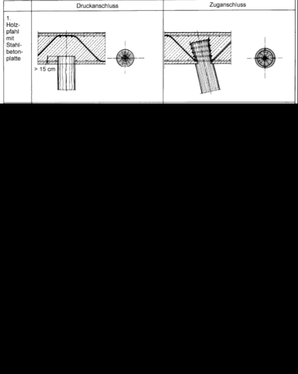
I will suggest R.C. cap ..the first dteail for RC cap from the book (Franke, E.: Pfähle. In: Grundbau-Taschenbuch Teil 3, 5. Auflage,)

Second picture,the use of wooden cap at atimber pier . This detail from the book (Clarence DUNHAM, Foundations of structures 1962)


holzephale_mit_stahlbeton_platte_lba2fc.png
timber_pier_ctrctj.png
 
For small load, the lost art - wood key with wedge might just work.
 
Here's a timber pier for a highway bridge. I got this from an Arkansas DOT website that has plans of old bridge. It's a great site; all types of bridge plans. Amazing how 100 years ago they could build a long span bridge with 10 sheets.

Link
 
 https://files.engineering.com/getfile.aspx?folder=63bfdcdf-ea14-458d-9088-158075db8c53&file=(01701)_Wildcat_Creek_Bridge.pdf
Status
Not open for further replies.

Part and Inventory Search

Sponsor