Continue to Site

Eng-Tips is the largest engineering community on the Internet

Intelligent Work Forums for Engineering Professionals

  • Congratulations KootK on being selected by the Eng-Tips community for having the most helpful posts in the forums last week. Way to Go!

Timber total deflection criteria 3

Status
Not open for further replies.

l______40mm______l

Structural
Jul 19, 2020
16
Hi,

I'm an Australian structural engineer and am currently trying to define the total deflection criteria for a timber floor. In the Australian standard AS1720.1 you determine a modification factor for creep (j2). The dead load deflection is noted by δG and the live load deflection is noted by δQ.

TEDDS design software uses a total deflection criteria of j2 x (δG + ψsδQ), ψs being the short-term component of the live load (0.7 for typical floor applications).
Structural toolkit design software uses a total deflection criteria of j2 x (δG + ψlδQ)+ ψsδQ, ψl being the long-term component of the live load (0.4 for typical floor applications).
Both formulas seem to be over-conservative to me as I thought that the criteria would be j2 x (δG + ψlδQ)+ (ψs-ψl)δQ, as you've already accounted for part of the live load in the creep formula.

I'm not an expert in Timber so any advice or comments would be greatly appreciated.

Cheers.
 
Replies continue below

Recommended for you

You're right.

Edit: Appendix B might let you push even harder.
 
We have similar factor in the NZ timber standard (a k2 factor) (and obviously share the same loadings standard), and it's generally interpreted as being just j2 x (δG + ψlδQ) here for the long term deflection case.

But your interpretation with the difference between short and long term factors being added onto the longer term deflections totally makes sense when considered as applying short term load in the long term case sometime in the future after all the permanent creep has occurred. Really interesting, as I've never considered it like that before, but totally makes sense to me as the logical way to apply short term load at longer timeframes.

You're right that the Tedds and Structural toolkit formulations seem to misinterpret the intent of the long term creep component, overcooking it a fair bit by the looks of it. But depending on actual configuration could be conservative obviously, but given you are generally governed by deflections in timber design you don't want to lump conservatism on conservatism generally as you'll just not compete with others who are more lax in their interpretation of the requirements.
 
Thanks Steveh49 and Agent666 for providing some clarity. It's good to hear how others are interpreting the code
 
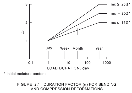
Thanks Tomfh, that makes a lot of sense to break it up like that. As the creep factor is set on a logarithmic scale a 5 month duration gives about 1.8 so it's pretty close to Tedds j2 x (δG + ψsδQ)(figure 2.1)
j2_factor_xxr1x9.png
 
I don't adopt the method Tomfh does. To me, the long-term component of live load is meant to be the part that is subject to creep. For example, compare to concrete: AS3600 clause 8.5.4. In the definition of F_d.ef, the creep multiplier is only applied to the long-term live load component. This equation is the same as 40mm's [short term minus long term] version, just rearranged.

The 0.8 factor for ultimate design isn't suggesting that the ultimate load is in place for five months. That would mean the design criteria were enormously wrong, not something an adjustment factor is meant to cover. The 0.8 represents an average value given that the dead load and part of the live load is permanent/sustained (factor = 0.57) while part is short duration (factor = 0.94 to 0.97).
 
To me, the long-term component of live load is meant to be the part that is subject to creep

This is how I've always interpreted it as well, obviously inclusive of the dead load component as well though causing the creep.

It's just a measure to determine after some period how much creep occurs under an average more realistic longer term average load of 0.4Q * 2. It could vary between 0.0Q and 1.0Q at instantaneous time periods over the life of the structure, but as an average loading over time, loading studies show long term factor * Q could be applied throughout for same effect essentially.

The 0.7Q short term load is more about the instantaneous condition regarding deflections, not about also determining some additional creep because it was present for longer than 24 hours. So applying this load after longer term creep had occurred seems correct to me to see the maximum deflection after some period of time (creep + instantaneous). I considered this more correct than the way I have always done it anyway which is the generally accepted approach I noted in my first reply.

This is why for certain occupancy's where studies show a higher longer term average load (storage and so forth), the factors are obviously different/higher.

Ultimate loading is an extreme event by comparison, and the psi factors account for the probability of SLS loads being quite a bit less extreme. From the commentary:-
image_etmzrj.png
 
Yeah, you guys are right. 0.4 already covers it.

I was wrongly thinking of 0.4 as a baseline with occasionally loads in excess of 0.4. Whereas 0.4 is an average that already includes the occasional loads in excess of 0.4.
 
If I had ever read the part in section 2.4.1.2 about creep recovery, I forgot it. The whole section is helpful in understanding the code requirements.

Overall though, all the uncertainties probably dwarf the exact load used. Eg appendix B suggesting you might need to halve the elastic modulus for deflection-critical elements. I'm sure creep can also be a lot more than the specified value.
 
In materials science, creep (sometimes called cold flow) is the tendency of a solid material to move slowly or deform permanently under the influence of persistent mechanical stresses. It can occur as a result of long-term exposure to high levels of stress that are still below the yield strength of the material.

Note that creep happens on material under SUSTAINED LOAD, it is conservative to consider portion of the live load is persistent throughout the service life.

Sustained loads are the loads which act throughout the service life of the structure. These loads include the self weight of the structure and superimposed dead loads on the structure such as parapets, crash barriers, surfacing and fills over the structure. These loads are responsible for creep and cracks in the structure. Earth pressure can also be treated as sustained load in design of retaining structures. Sustained loads are also called quasi permanent loads.
 
professor,

Can you elaborate on the Timoshenko theory, regarding creep? Thanks.
 
Status
Not open for further replies.

Part and Inventory Search

Sponsor