Continue to Site

Eng-Tips is the largest engineering community on the Internet

Intelligent Work Forums for Engineering Professionals

  • Congratulations waross on being selected by the Eng-Tips community for having the most helpful posts in the forums last week. Way to Go!

Timber Truss Connection 2

Status
Not open for further replies.

DaveHolder

Structural
Jun 13, 2013
80
Hi All,

I am looking for a suitable connection , it is a bit tricky.. I need to connect the top member to the bottom member (beam), also, where the top members meet, however, as the ATFN conceal beam hanger to timber beam junction is obstructing it is not possible to fix the top member to the bottom with plate. Screws alone don't take the loads. Any suggestions?


Thanks
 
Replies continue below

Recommended for you

You should be able to make some sort of large plate work to connect the top chord to the bottom chord. The concealed bit does not take up that much real estate.
 
XR250 said:
You should be able to make some sort of large plate work to connect the top chord to the bottom chord. The concealed bit does not take up that much real estate.

I totally agree with you. The question in this case, however, is how to connect the cross and outrigger beams to the truss.

 
Has anyone got any experience in timber connections seems to be a tricky one as there's hardly any response.

 
If those beams extend beyond the truss, then I don't believe there is an option for that.

If they end at the truss, there's multiple face mount hanger options that would likely work for you that don't need to go to the top of the beam. Check out Simpson Strong-Tie HGUM and LGUM hangers for examples.
 
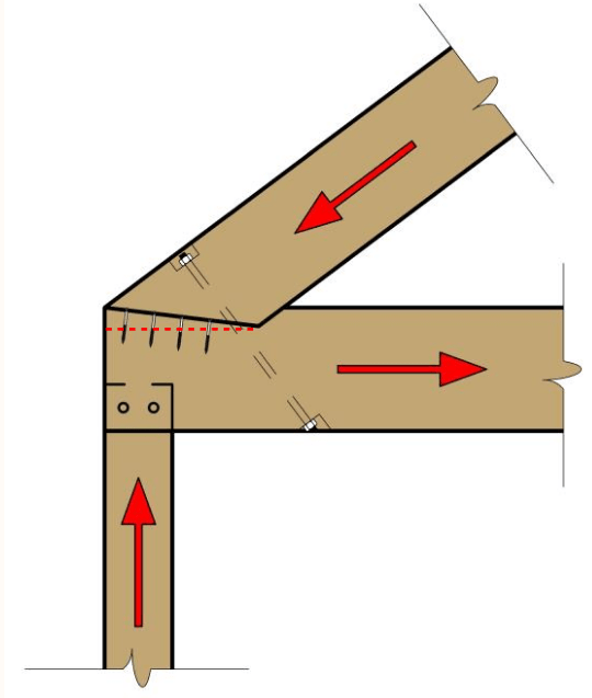
Traditional joints use a birdsmouth or some other beveled cut to allow some of the rafter thrust to bear on the notched face of the bottom chord.

Modern connection designers use the timber screws as shear reinforcement to resist the potential block shear/longitudinal shear failure mode (even if the bearing capacity calcs out).

The image below is from Jim DeStefano's timber connection presentation, which I would highly recommend (the red dashed line was added by me):
Screenshot_2022-07-11_092233_wlrxcj.png
 
Thank you guys for your help.

The beams are not extended they are actually cut to fit either side of the truss. To create a 20cm overhang.

How do you fix the face mount hangers to support the cross timber beams if we ignore the overhang and use the bolted plate?
 
If you're using a steel plate at the truss joint, could you not just get a knife plate added to it, or a beam saddle?
 
Thank you Jayrod12,

jayrod12 said:
If you're using a steel plate at the truss joint, could you not just get a knife plate added to it, or a beam saddle?


If you don't mind, could you please draw a sketch that shows how to attach a knife plate to a bolted plate?

Thanks
 
I could, but before I do that, I want to make sure that I'm understanding your situation correctly.

You are going to have a heavy timber truss, where the joint connections are externally installed bolted plates (i.e. one plate each side with through-bolts correct?)
 
jayrod12 said:
You are going to have a heavy timber truss, where the joint connections are externally installed bolted plates (i.e. one plate each side with through-bolts correct?)
Yes

 
How much truss action are you really counting on here? It's hard to tell based on the pictures here, but my approach on something of this scale would typically be to just design the cross beam to take the entire point load of the ridge beam. Then the "top chord" members are not required and it simplifies the framing overall.

I think that is the way to go, especially because based on your rendering it doesn't look like you would have the top chord exposed anyways.

What is the span of your bottom chord? Could you size that beam to support the king post and ridge beam above without any truss action?
 
Ok.

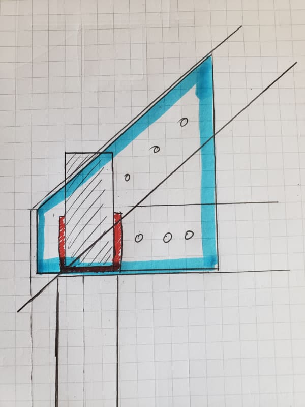
Again, assuming that the beams don't need to project beyond the truss, I feel you could do something like the attached. The blue outlines the extent of the gusset plate at the joint, and the red is a saddle. This saddle could alternately be a T-shape for a hidden knife connection with a bottom bearing plate.

20220711_134736_cq5ta9.jpg
 
ryaneng said:
How much truss action are you really counting on here?

Dead Load 1kN/m UDL and 6kN from ridge beam
Imposed load 0.5kN/m UDL and 3kN.

The timber beam size to take 6kN dead load and 3kN imposed load for 5.2m span would be 150x300mm deep.
 
Thank you jayrod12,

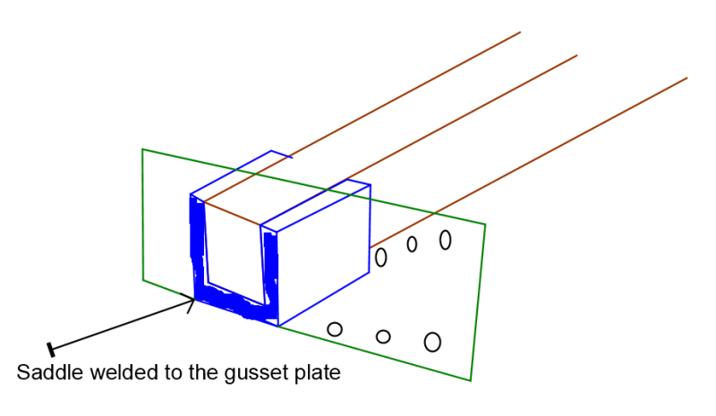
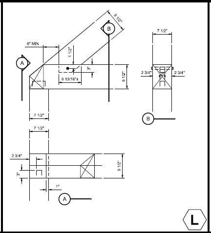
Is this what you mean below welding the saddle to the gusset?

Saddle_n22ssi.png
 
Clipboard01_ssmgco.jpg


So strange to see the singularity approaching while the entire planet is rapidly turning into a hellscape. -John Coates

-Dik
 
Status
Not open for further replies.

Part and Inventory Search

Sponsor