Continue to Site

Eng-Tips is the largest engineering community on the Internet

Intelligent Work Forums for Engineering Professionals

  • Congratulations IDS on being selected by the Eng-Tips community for having the most helpful posts in the forums last week. Way to Go!

To all, I have several drawings th 1

Status
Not open for further replies.

SBRIRONMAN

Mechanical
Feb 26, 2011
5
To all,
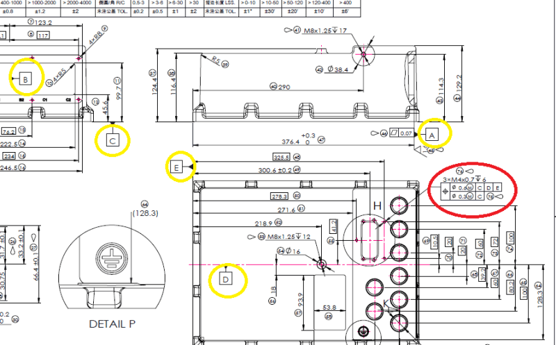
I have several drawings that I am checking for our engineering group and the source that
is making the drawings has GDT on a specific tapped hole.

I need some insight to his GDT callout on the tapped hole circled in red.Better yet,
and explanation why : true position / dia 0.6 / max material condition / c /d/ e
/ dia 0.3 / max materialcondition / c

If someone can maybe explain what he means by this, I would appreciate it. I do not want
to send the drawing back to (China ) and have them remove the GDT if it is not necessary.


Thanks
GDT_on_housing_enucnx.png
 
Replies continue below

Recommended for you

It's a Feature Control Frame, not a GDT. It means what it says; there is no way to guess why they chose this without seeing their write up of the dimensioning and tolerancing analysis.
 
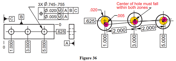
There are several GD&T books out there explaining this symbol called "Compound position":
Capture_kky4c2.png

The composite position symbol is entered once and applies to both upper and lower segments. The lower segment is always a subset of the upper segment.
The upper segment is called the “Pattern-Locating Tolerance Zone Framework (PLTZF)”. It locates the pattern of features as a group within a larger tolerance zone than the lower segment.
The lower segment is called the “Feature-Relating Tolerance Zone Framework (FRTZF)”. It locates each feature within the pattern for a feature-to-feature relationship. If the lower datums match the upper datums, then the lower datums will override the upper datums for orientation tolerance size, and only location for the feature-to-feature.
Any datum listed in the lower segment must match the datums in the upper segment in the same order of precedence to govern the orientation of the lower segment. The “M”, “L” and RFS modifiers must also match.
In Figure 36, composite position allows the pattern to be located from the datums “B” and “C” within .020 at MMC to a maximum of .030 at LMC. Datum plane “A” in the lower segment will override datum “A” in the upper segment for perpendicularity. The lower segment also controls the holes to each other within .005 at MMC to a maximum of .015 at LMC

"For every expert there is an equal and opposite expert"
Arthur C. Clarke Profiles of the future
 
The feature control frame you have noted is a multiple single segmentcomposite positional tolerance, if you have access to the y14.5-2009 standard it is contained in section 7.5.27.5.1 - it is a method of simultaneously controlling relative position of a pattern both to the datums (pattern to datum) and itself (feature to feature within the pattern).

It looks like your datum [D] is applied to a midplane/centerline of some sort - this is not a correct application of a datum, datums must be applied to physical part features. Your datum may have the same issue, its not really clear what its even applied to - however it is not in the Feature Control Frame you have indicated.

Edit: oops, skimmed it too fast, it is composite tolerance sorry.
 
CH beat me to it and provided a much better explanation, I should just add that any datums added in the lower segment (FRTZF) will control orientation/rotation of the entire pattern relative to the datums specified. For example in CH's figure the inclusion of datum [A] in the FRTZF controls rotation about [A] which means the pattern tolerance zones must be perpendicular to [A] but free to translate within the PLTZF - the addition of datum would mean that the entire pattern is controlled in rotation to as well, but is still free to translate within the PLTZF.


CheckerHater said:
If the lower datums match the upper datums, then the lower datums will override the upper datums for orientation tolerance size, and only location for the feature-to-feature.

CH - could you elaborate on what you mean here? I'm not sure I quite follow, I wasn't aware of such a rule.
 
CH,

Sorry for the triple post I figured it was better than editing, just wanted to say I re-read your post and I realize we were both sort of stating the same thing, however your usage of the word "override" threw me through a loop. Its a bit confusing to think of it that way, is there a particular reason why you are phrasing it like this?
 
"Override for orientation / perpendicularity"
Maybe not the best choice, but how will you say that hole should satisfy perpendicularity from lover frame and not from upper frame?

"For every expert there is an equal and opposite expert"
Arthur C. Clarke Profiles of the future

 
CH,

I would say that they are satisfied simultaneously, why does it have to be one or the other? The perpendicularity control still applies to the tolerance zone created by the upper frame, even if it is repeated in the lower frame.
 
If perpendicularity goes outside of .005, the part is not compliant. So it is one and not the other.
Another word may be "refine", but it has enough bad rap as well.

"For every expert there is an equal and opposite expert"
Arthur C. Clarke Profiles of the future

 
Since you're dealing with a threaded hole - one more thing that might be a useful piece of information: according to ASME-Y14.5 -2009, since there is no note such as "MAJOR DIA" or "MINOR DIA" beneath the position feature control frame, the position tolerance applies to the Pitch Dia. of the threaded hole. This is the default rule in such cases.
 
I have no problem with the word refinement, I didn't realize there were issues with using it as is perfectly describes the situation.

I sort of get what you are trying to say, I just think the term "overriding" is misleading and I don't believe that thinking of them as simultaneous is contradictory, consider it this way:

The .020 tolerance sets up the larger PLTZF tolerance zone. The .005 tolerance sets up the smaller FRTZF tolerance zone which can float within the PLTZF. The actual axis of all the holes must lie ENTIRELY within BOTH zones. If the perpendicularity of one or more of these axes is greater than .005 then it no longer lies entirely within both zones and is not compliant. I don't really think overriding comes into play - both must be considered and satisfied simultaneously, if both are not satisfied then it is not compliant.
 
Status
Not open for further replies.

Part and Inventory Search

Sponsor