Hi, I was given a lathe design by my professor to analyze.
The lathe uses two tapered roller bearing with different sizes in a back to back arrangement which is 340mm apart.
The lathe will then be fitted with a testbar and it's runout will be calculated against the lathe bed.
The spindle is required to have an accuracy that follows the code number G6 from ISO 1708:1989 "Acceptance conditions for general purpose parallel lathes — Testing of the accuracy".
The standard states that the runout shall not pass 0,005mm for a measuring length of 100mm (from spindle nose).
I'm allowed to assume a perfect bed and test bar, so that only the seatings (on the spindle), the housings (on the headframe), and the bearing itself that contributes to the spindle's accuracy.
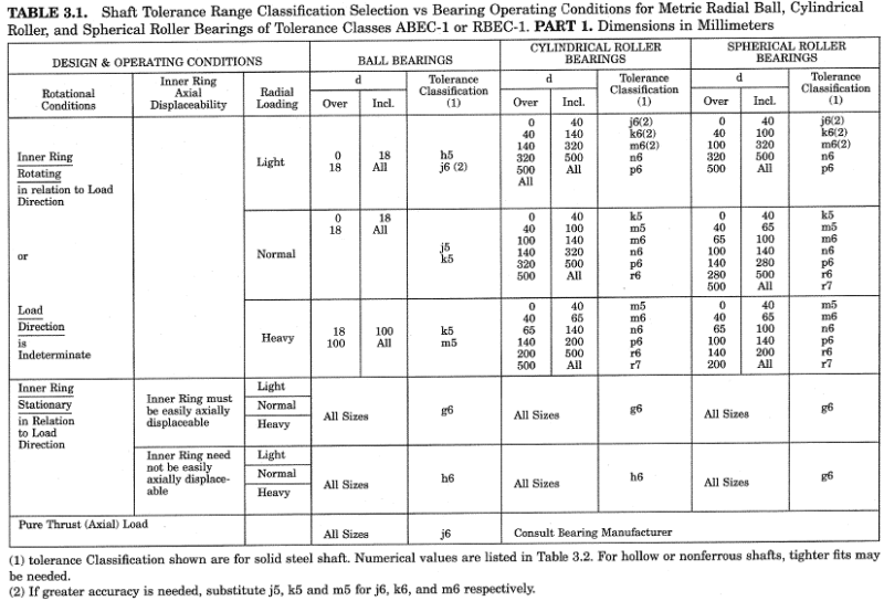
I'm wondering if there's any book/reference/paper about how to choose the correct bearing class to fit that standard and how to design the tolerance for the bearing seatings and housings.
I tried modelling the system as lines but i'm not sure if this is accurate enough.
We would like to also figure out how different tolerance values affect the runout accuracy through that model and finally if the preload affects/breaks the whole calculation.
Feel free to ask for more details of the bearing system. Any references regarding similar topic is appreciated, thank you.
The lathe uses two tapered roller bearing with different sizes in a back to back arrangement which is 340mm apart.
The lathe will then be fitted with a testbar and it's runout will be calculated against the lathe bed.
The spindle is required to have an accuracy that follows the code number G6 from ISO 1708:1989 "Acceptance conditions for general purpose parallel lathes — Testing of the accuracy".
The standard states that the runout shall not pass 0,005mm for a measuring length of 100mm (from spindle nose).
I'm allowed to assume a perfect bed and test bar, so that only the seatings (on the spindle), the housings (on the headframe), and the bearing itself that contributes to the spindle's accuracy.
I'm wondering if there's any book/reference/paper about how to choose the correct bearing class to fit that standard and how to design the tolerance for the bearing seatings and housings.
I tried modelling the system as lines but i'm not sure if this is accurate enough.
We would like to also figure out how different tolerance values affect the runout accuracy through that model and finally if the preload affects/breaks the whole calculation.
Feel free to ask for more details of the bearing system. Any references regarding similar topic is appreciated, thank you.