Continue to Site

Eng-Tips is the largest engineering community on the Internet

Intelligent Work Forums for Engineering Professionals

  • Congratulations GregLocock on being selected by the Eng-Tips community for having the most helpful posts in the forums last week. Way to Go!

Tolerance on the outer diameter and end of threaded pipe

Status
Not open for further replies.

Znjmech

Mechanical
Dec 19, 2016
94
Hi All

I have a part that should be connected to a water pipe. I see a tolerance of -0.2 to -0.3 as you can see in the image on the outer diameter of the exit pipe of my part that will be connected to the water pipe. I have just put the dimensions that are relevant to my question. I have seen this tolerance on an existing design. I don't know two things : what is there the small taper before the thread starts? and why should we have such a tolerance?
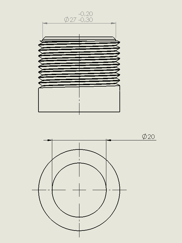

pipe_nfadzm.png
 
Replies continue below

Recommended for you

I can only guess that the taper section is actually the sealing surface where it meets the end of the hole into which it is screwed. We need to see the whole joint to make sense of it.

It appears to be a straight thread so needs a separate sealing surface.

Remember - More details = better answers
Also: If you get a response it's polite to respond to it.
 
It's 'your' part; why are you asking _us_ about its features?

What did you copy that termination from?
Maybe documentation for that product will answer your questions.


Mike Halloran
Pembroke Pines, FL, USA
 
@Pennpiper

Thank you very much. you are right, it should have a taper ! only thing that when I opened the relating page , it was for stair banister railings. But I think I am sure what should I find.

@Mike Halloran : Usually if a young engineering team puts hands on old drawings, doesn't tend to do the same engineering but copies the same dimensions and notes, without noting what is happening and not being sure what they can remove. I wanted to do some more investigation. Such documentaion doesn't exist for the part connection( other normatives on other characteristics do though). So for the connection, I think I have to follow pipe fitting standards, yet I don't understand that strange tolerance
 
It's common to find a taper in that location, but it comes from a rotating wheel pipe cutter, and is not normally controlled or even shown on a drawing. So it must have some other purpose, which so far is not apparent.

It's also common to find a separate bevel on the same end, applied after threading to remove the sharp projecting half-thread shown in your drawing. That fragile half-thread facilitates cross-threading and leaks.

I suggest getting on the phone Real Soon Now and talking to any surviving old timers you can find; maybe someone will remember why the joint looks the way it does.

In the meantime, we here might be able to make better guesses, given photographs and/or fully dimensioned drawings of the parts.


Mike Halloran
Pembroke Pines, FL, USA
 
Thank you very much Mike, I will try to do that. I have limitations(I can not share the photo or the exact application etc)

But your help was quite useful for me. That I did not know that half threads might create problems.
 
Status
Not open for further replies.

Part and Inventory Search

Sponsor