Continue to Site

Eng-Tips is the largest engineering community on the Internet

Intelligent Work Forums for Engineering Professionals

  • Congratulations KootK on being selected by the Eng-Tips community for having the most helpful posts in the forums last week. Way to Go!

TOLERANCE STAK UP 1

Status
Not open for further replies.

Michael Boble

Aerospace
Apr 30, 2020
9
Hello everyone.

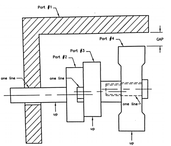
I am practicing with the Tolerance StackUp theme to determine the GAP of the following image:
PPPP_ft2wcg.png


I have three proposals so far of the routes that can be used, however I would like to know your opinion to see if my deductions can be correct (I share my 3 proposals below) Any other route that occurs to you would be accepted.

12_psc6ag.png


Thanks for your support
(An apology for my drawings, I have a little trouble representing it on the computer)
 
Replies continue below

Recommended for you

Michael,

Without knowing how the tolerances are applied it would just be a guess, or maybe a plausable path but not necessarily the correct one. Unless the "up" and "one line" notation means something, I'm not familiar with that. I guess UP shows the direction of the worst case stack. Tough to even suss out how they interface.

Also curious why you deleted your last post after I posted a pretty clear cut answer to your question.
 
As Chez311 mentioned, it's difficult to say without knowing where play or looseness might be occurring -- we don't know where the contact points are from one component to the next.
However, I think your answer will unintentionally be negative, because your origin for the stack path is on the upper side of the gap you're solving for. (With the up direction being positive, the gap lies in negative territory.) Best to start from the lower side of the gap and go from there to connect the vectors.

John-Paul Belanger
Certified Sr. GD&T Professional
Geometric Learning Systems
 
I believe the "ups" represent the direction of the radial shift of the components in the assembly. The "one lines" represent points of contact between the components. So the "GAP" seems to represent the smallest possible clearance between "Part#1" and "Part #4".

As it was suggested, it is impossible to answer the question without exactly knowing the tolerances applied to each of the components.

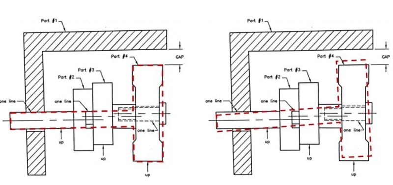
Additionally, if the "GAP" is indeed intended to represent the minimum possible clearance between "Part #1" and "Part #4", I hope that the book or training material, from which this exercise has been taken, gives a disclaimer to ignore all 2D effects in the assembly. The picture below shows one of the reasons why it is needed.

capture-2_bvxx5i.jpg
 
Status
Not open for further replies.

Part and Inventory Search

Sponsor