Eng-Tips is the largest engineering community on the Internet

Intelligent Work Forums for Engineering Professionals

Torsion Bars In series 1

Status
Not open for further replies.

GordonPask

Automotive
May 6, 2021
3
0
0
IT
Hello,
I am looking for an advice on how to would the following system of a series of torsion bars would behave in terms of effective stiffness in various modes: single wheel hop, roll and double wheel-hop.
The system is as follows:
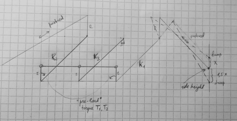
There are three torsion bars K1, K2, K3 of the same length L positioned parallel to each other at equal distances, imagine there are two bearing close to both ends of each of them that allow only rotation, so bars don't slide or turn and remain parallel.
At one end of all three bars there would be a rocker of short arm length r pointing upwards in our "ride height" position. So all three small rockers are parallel.
The other ends of these rockers are connected between each other by a long bar with three holes, so if we turn one of the torsion bars, the remaining two will turn by the same degree.
Now on the other end of the bars the situation is as follows: The middle bar is connected at that end to chassis, while the "corner" bars have rockers of bigger arm R that connect pushrods to input wheel movement into your system.
Now to have droop springing, we would have applied initial torque t1 and t2 (at ride height) to the "corner" bars (for example it could be achieved by having the adjustable lengths between holes on the bar that connects small rockers).
How would such system behave when we apply single wheel bump adding the torque R*f1 to the end of the corner bar?
What would happen in double hop (such as heave or pitch)?
In roll?

Thank you
Gordon

 
Replies continue below

Recommended for you

Drawing, please.

If I understand correctly, the three torsion bars are longitudinal in the vehicle, the outer one on the left side connects to the left suspension and the outer one on the right side connects to the right suspension (thus in compression, the sense of rotation is opposite when viewed from the front), and then instead of an anchor at what's normally the chassis end, you have a linkage connecting to the center one and the opposite end of that is the chassis end.

If that's the case, then in two-wheel bump, the center torsion bar doesn't do anything, and what's normally the chassis end of the left and right torsion bars cancel out their applied moments, and it acts the same as whatever the spring rate is of the outer bars on their own.

In roll, the (let's say) left "what's-normally-anchored" end transfers some of its moment to the other two, so instead of acting as an antiroll bar, it acts like a "pro-roll" bar. The suspension is softer in roll than it is in two-wheel bump.

That's ... unusual.

Question 1, did I understand it correctly.

Question 2, WHY?
 
Brian, thank you for the reply, and I apologise for not having made the drawing immediately to clarify things. The suspension has been described to me by a friend of mine who presented it as what their suspension team is working on for the FSAE prototype. Certainly there is some broken phone transmission, but I am certain that the core structure is like this:

IMG_20210506_224750_zpiysw.jpg


So I think your description of the system corresponds quite well to the drawing, but I am not completely sure about what is happening there in terms of forces.
 
Static, the left and right bars take the weight of the vehicle, the connecting bar is in balance so the center bar has no load. In two-wheel bump or droop, same thing, center bar does nothing. In roll, the center bar takes up the full difference in load between the left and right sides. It will have lower at-wheel spring rates in one-wheel bump or in roll than in two-wheel bump. It's the opposite of anti-roll...it's pro-roll.

Why?

What are they trying to achieve by doing this?

Objective?
 
They are trying some mode decoupling, but I have no other information. Just remained puzzled for few hours trying to figure out what's going on and their intentions as it seemed counter-intuitive to me.
I would imagine that a damper is mounted between the bigger rockers that as usual would work in hop only, but that's nothing new... A roll-only damper could be placed maybe between chassis and the small middle bar rocker?...

It will have lower at-wheel spring rates in one-wheel bump or in roll than in two-wheel bump
– the fact that one wheel bump has lower spring rate that two-wheel one seems good to me and pretty usual no?
but about roll... in roll we are actually twisting the middle bar (which as you said is not present in double wheel hop and I imagine is experiencing the added torque of the rising wheel in single hop, as preload torques left and right more or less cancel each other?), doesn't its stiffness, and how it relates to corner stiffnesses determine the bahaviour, shouldn't we look more carefully at actual deflections and rates of each bar?

 
Certainly you can get some separation in tuning between heave (two-wheel motion) and roll (one-wheel motion) but the wheel rate in one-wheel motion is always going to be less than in two-wheel motion with this setup, because in two-wheel motion you are using the spring rate of the primary torsion bar only (the one that a "normal" torsion-bar setup uses), whereas in one-wheel or roll motion you are going to have that in series with the spring rate from the middle spring, so it is always going to be less.

If you have completely independent suspension with no anti-roll (or pro-roll!) bar, the wheel rate for two-wheel and one-wheel bump (and pitch and roll and heave) is the same. If you have the conventional arrangement which uses an antiroll bar, then the two-wheel or heave motion doesn't use the antiroll bar (it just rotates as a unit without twisting) whereas one-wheel or roll motion does, so the wheel rate for one-wheel or roll motion will be higher than for two-wheel bump ... and this is the usual arrangement.

I'm not necessarily saying that what they're suggesting is "bad", I'm just saying that this is what it "is". That it isn't the way things usually go, means someone had better be asking the right questions.

Do they like body roll? (See: Citroen 2CV, Renault 4, among others)

Is it an application where body roll matters less than articulation? (Rock crawlers, maybe other forms of off-road driving/racing - Not Formula SAE)

Torsion bars tend to be a pain in the tail for packaging, in case they haven't found that out already. The rear suspension of some of the old French cars sorted it out nicely by using pure trailing arms with the torsion bars cross-car. VW air-cooled Beetle front suspension with double pure trailing arms packaged them pretty neatly cross-car between the upper and lower trailing arms, but the geometry is awful. Upper and lower wishbone suspensions plus torsion bars usually leads to longitudinal torsion bars wanting to either share space with other stuff underneath the vehicle or forcing the whole floor to be raised up to make space for them. Not too bad in a separate-frame-and-body truck. In a race car meant for pavement/tarmac, where you want the driver to sit as low as you can make it to get the center of gravity down ...

If the intent is to get a better ride versus handling compromise, I'd be more inclined to study the effects of making front-rear connections. Study material: Citroen 2CV, British Leyland Hydrolastic and Hydragas. Pay attention to addressing pitch during braking by building anti-dive geometry into the front suspension and anti-lift geometry into the rear suspension. Some of those cheap old cars were much more ingenious than it may first appear.
 
This smacks to me of 'they do it in F1, so it must be the best approach for FSAE' which is, unfortunately, the approach a lot of FSAE teams take.

The arrangement above is highly similar to the way most F1 car suspensions currently work at a very basic level. Differences between their concept and a current generation F1 car would be motion ratios, and the addition of a LOT of controls (ie passive suspension hydraulics that complicate all the interactions).

 
F1 has a particular problem in that it is desirable for aerodynamics to have as little ground clearance as possible, but it is not allowed to be zero. They can get away with extremely high spring and damping rates because they are operating on smooth tarmac. They don't care about ride quality. A suspension design that takes up a curb strike on one side and uses part of that to apply downward force to the tire on the other side (to raise up the whole vehicle) isn't necessarily terrible. They have little body roll despite this because the center of gravity is very low and the spring and damping rates are generally off the scale.
 
Brian, totally agree that this scheme is reasonable for an F1-type scenario (although F1 suspensions are of course exponentially more complicated) and is probably less than ideal for an FSAE car.

All I was getting at is that I suspect that the FSAE suspension designer in question saw one of the billion pictures of F1 front suspension arrangements that are out there, and applied the 'all F1 solutions are applicable directly to FSAE cars without significant revision' approach that seems to be common among FSAE teams which aren't operating among the top tier of the program (where in my experience the level of engineering is remarkably high, especially considering it's all done by students).
 
Status
Not open for further replies.
Back
Top