Eng-Tips is the largest engineering community on the Internet

Intelligent Work Forums for Engineering Professionals

Torsion on a flexible diaphragm 1

Status
Not open for further replies.

KHoff

Structural
Aug 20, 2013
60
0
0
US
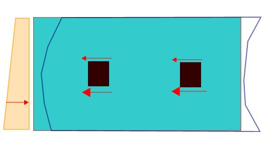
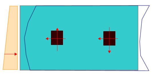
I have been tasked with site adapting a 5 story office building (originally built in Iowa) to be constructed at a new site in Nebraska. The original design (done by another engineer) utilizes two concrete shear towers for lateral, located near the center of the building at approximately third points along the length of the building. There are no moment frames or braced frames at the perimeter. The roof diaphragm is wide rib metal deck, which I would typically assume to be flexible. As far as I can tell, the only way the original engineer could get lateral load distribution to work at the roof is assuming the diaphragm resists some amount of torsion. I typically try to avoid that with a flexible diaphragm.

Any recommendations on tackling how to analyze torsional strength/stiffness of a flexible diaphragm?
 
Replies continue below

Recommended for you

KHoff said:
Any recommendations on tackling how to analyze torsional strength/stiffness of a flexible diaphragm?

It's a peculiar thing but, essentially, any diaphragm that is cantilevered from the lateral resisting elements becomes "rigid" automatically for the purpose of load distribution by virtue of equilibrium. That, regardless of it's actual stiffness. I don't recall if maximum aspect ratios exist for cantilevered diaphragms in steel as they do for wood but I'd be thinking along those lines regardless. 1:1 ideally or, at worst, 2:1 for me unless discrete horizontal bracing were being installed. The main things with using cantilevered decks are:

1) Look at column drifts that account for cantilever deck lateral displacements.

2) Be rigorous in your treatment of chords and collectors for your cantilevered diaphragm bits.
 
By definition, a flexible diaphragm cannot redistribute loads via torsion. So if you idealize it as that (as per ASCE 7)....the game is over. However, there is a provision that you can treat it as semirigid (that is model the actual behavior) and look at it that way.

I've never been sure how they mean for you to do that (either numerically or by a FEA model)....but I think it is permitted since most diaphragms are neither 100% rigid nor flexible.
 
KootK - I agree that the diaphragm cantilevers in one direction, where it spans between the two shear towers and cantilevers past to pick up the rest of the roof. However, in the other direction there is really only one support location as the two shear towers are aligned. In this case, I don't see how the diaphragm could work without resisting some amount of torsion since there is only one support. Am I missing something?
 
I think that I would strive to tell a story such as the one of the two shown below. Probably the second.

OP said:
I don't see how the diaphragm could work without resisting some amount of torsion since there is only one support. Am I missing something?

I believe that what you'rer missing is that the whole rigid / flexible dog and pony show is really about:

1) the distribution of loads to various elements and;

2) NOT the capability of diaphragms to provide torsional resistance.

Bare metal deck diaphragms can and do resist torsion / in-plane moments when properly designed. In a way, the cantilever situation is a bit of a boon analytically. There's only one load distribution satisfying statics at the cantilever support. I such, you know the load distribution by virtue of equilibrium and do not have get fancy in trying to estimate. That said, cantilevered diaphragms are definitely crappier than simple span flexible diaphragms in terms of performance.

With available fee to support the effort, I'm a fain of WArose's semi-rigid modelling proposal too.

c01_uuqecm.jpg


c01_wiyop4.jpg
 
KootK - Thanks for the figures, that certainly aids in the discussion. The second figure would be my assumption for how the lateral load is distributed to the shear towers. I understand that flexible diaphragms do have some amount of torsional capacity and that in reality diaphragms are actually somewhere between 100% flexible and 100% rigid. I think I am getting hung up on how to analyze the flexible diaphragm for torsion since the typical engineering assumption is that there is no torsional resistance. The suggestion by WARose to do a detailed analysis of the diaphragm as semi-rigid seems like the most sound engineering approach, but if time/fee don't allow for that what is the best way to review the diaphragm for adequate strength & stiffness?
 
See my proposal below. In my opinion it would be:

1) Sufficiently accurate and;
2) On par with the level of rigor that we would expect from our peers.

With modern FEM software, it wouldn't be all that much more work to do semi-rigid. I like to keep things simple, though, unless I really feel that greater accuracy is justified.

c01_rjqq3f.jpg
 
Thanks KootK. I was not familiar with that kind of diaphragm analysis. I have purchased a copy of the SDI Diaphragm Design Manual to assist, and plan on tackling the problem as you suggest.
 
Status
Not open for further replies.
Back
Top