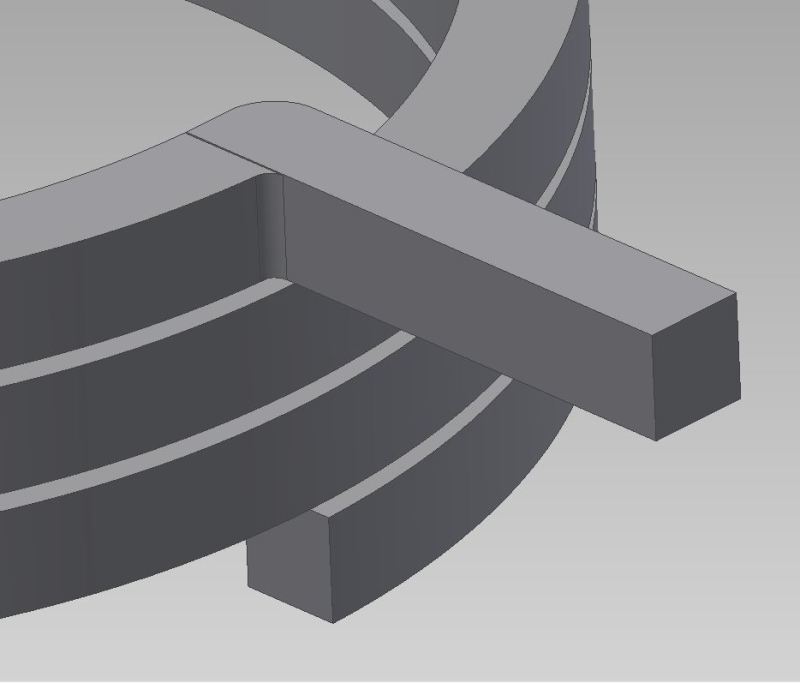
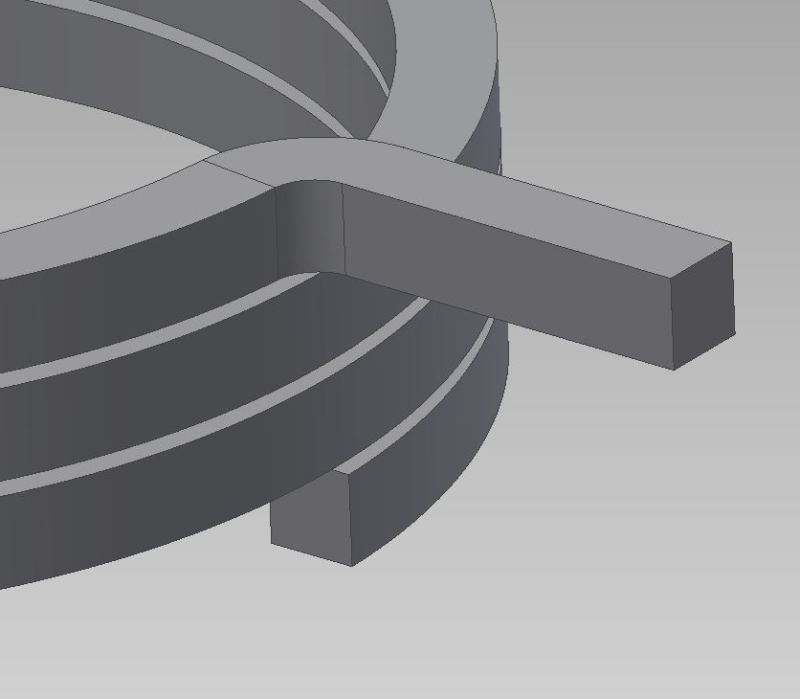
here is a SQUARE WIRE torsion spring. if you zoom in at the 90 degree bend, you can see the mis-match.
any way to do it better? or do it correct?
thanks.
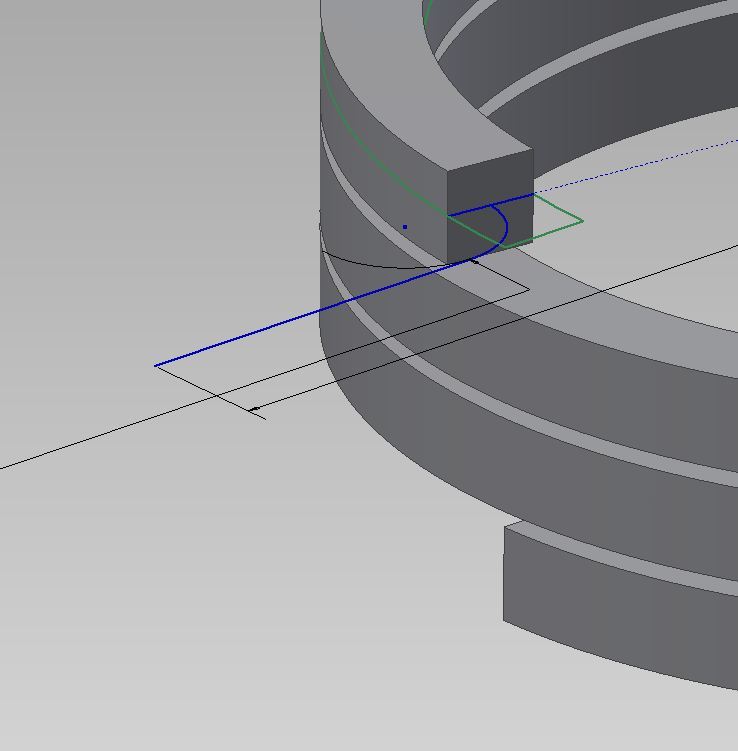
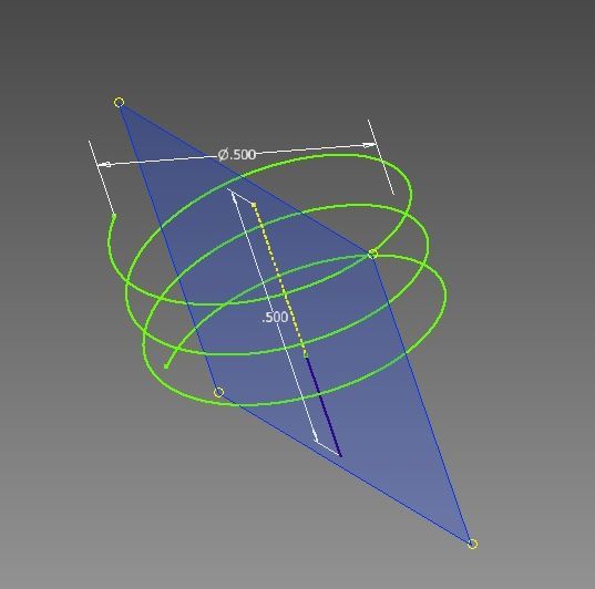
also, when i do a 3D spiral "line", how to line up the end with one plane?
any way to do it better? or do it correct?
thanks.
also, when i do a 3D spiral "line", how to line up the end with one plane?