Eng-Tips is the largest engineering community on the Internet

Intelligent Work Forums for Engineering Professionals

Torsional mode as fundamental mode in Multi-tower Building 1

Status
Not open for further replies.

Usman3301

Civil/Environmental
Jul 11, 2019
48
0
0
CA
Hi there,
It's going to be a long post but please bear with me. I am currently working on a multi-tower building with a common podium. For high-rise buildings, I am normally assigned the task of creating a finite element model with gravity loads properly applied so as to assist my senior, who takes over the model and carries out the dynamic analysis and from thereon to the design stage too. Meanwhile, I go back to working on other small residential projects.

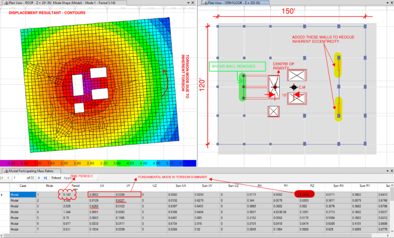
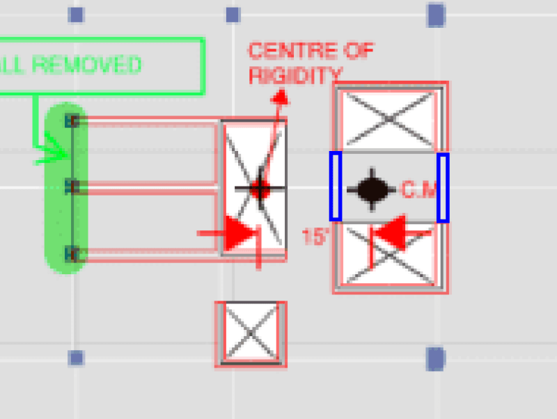
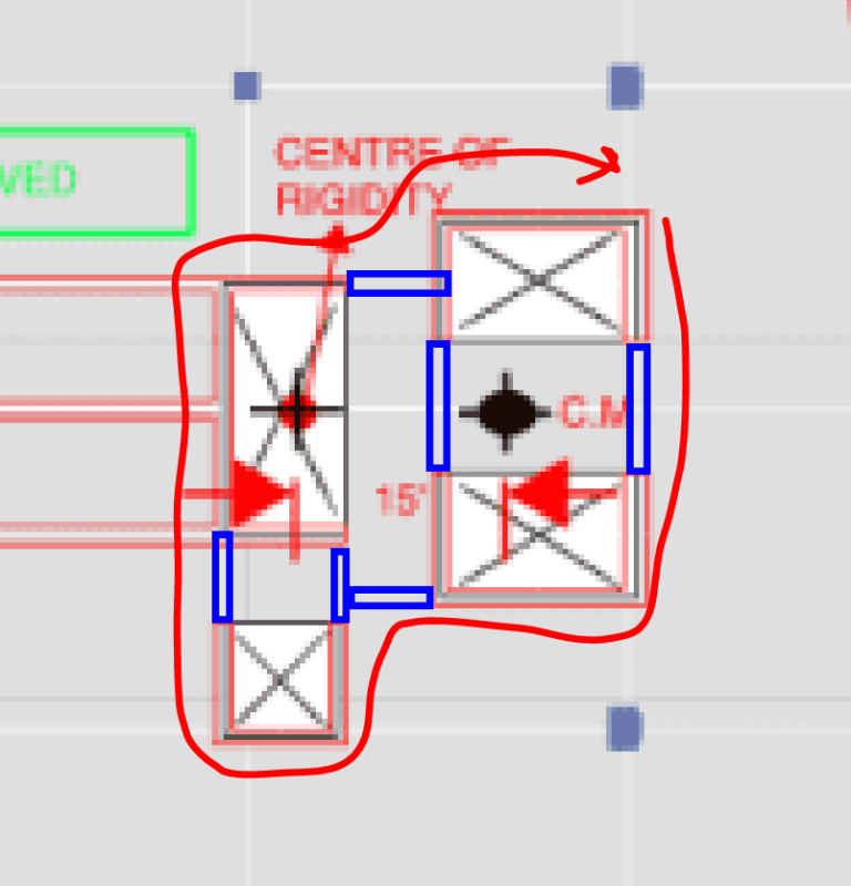
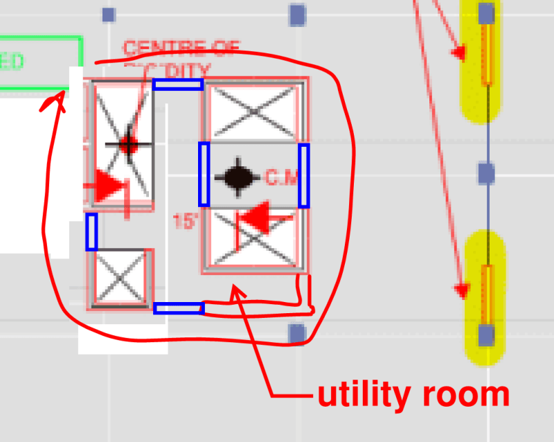
The problem is, my senior is on a leave for two weeks and my boss told me to work on the project and see if the current framing system works in our case. Although we are in an initial phase, my Boss has a meeting with the Architect tomorrow to discuss the basic framing system and layout of shear walls. I am worried that the current layout of shear walls isn't appropriate, given that most of our shear walls are concentrated in one half (left portion) of the tower. I have tried a number of different layouts, which involve adding shear walls to the right of the tower, removing shear walls from the left of the tower as explained in the image attached. Also, I am quite concerned about the impact both the towers will have on a common podium. Both towers have different masses and layouts and I believe both towers, if not have fundamental mode as translational and also in the same direction, will be out of phase which will consequently create very very high demands on the podium level.
Adding to the discussion involving shear walls that have been added on the right to counter inherent torsion, there's no way I can add any shear wall to the right due to architectural constraint.

I haven't previously modeled a multitower building and this is my first one. Initially, I modeled both towers with a common podium. But when I studied the results (modal results), it became quite clear to me that something is very wrong. Therefore I decided to analyze both these towers individually. Upon analysis, it became clear to me that the left tower has a "translational mode" as the fundamental mode, meanwhile, the right tower's fundamental mode is torsional and the time period (5.15 sec)for the right tower is also very high given that tower height above podium is around 280 feet.

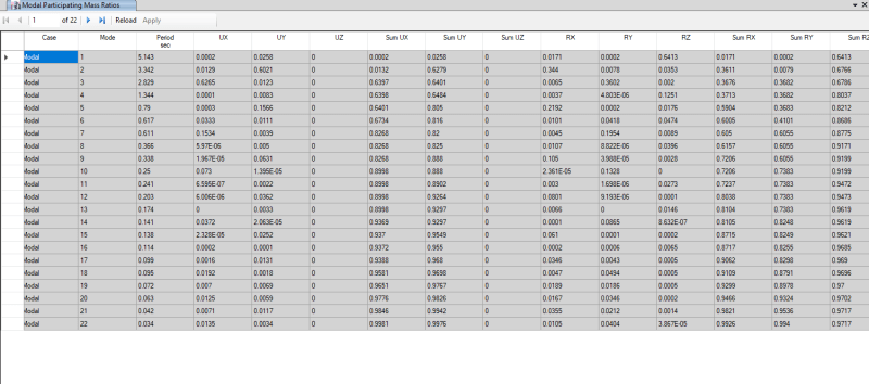
I have attached modal results and the basic layout of the right tower only.
Following are important parameters for this particular project:
Ss = 0.49
S1 =0.15
Seismic Design Category = D
Soil Profile = SD

Given the situation, kindly let me how I should go about this. I have to inform my boss whether our current configuration will work out or not.
If the current configuration isn't optimal, and there's a need to add shear walls to the right, I suspect the architect might have to re-do all his work. Therefore, kindly let me know if I am thinking correctly.
I have also attached the ETABS model for Right tower.


LAYOUT_OF_RIGHT_TOWER_ruypuq.png

E-T_2_ni0ckt.png

 
Replies continue below

Recommended for you

To what extent are your wall groups coupled? Coupling will get you some degree of closed section torsional stiffness which might help. I wouldn't sweat the common podium. That's a pretty common scenario and should be resolvable by some means.
 
@KootK
Let me know what exactly you meant by "extent of coupling". A bit embarrassed though because if I was in your place, I'd have been surprised too realizing that one doesn't know simple terminology.

BSc. Graduate
 
Yeah it looks quite soft in torsion with all the walls being concentrated near the middle. Whether it works or not is a complex question.

Why remove those green walls if torsion is a problem?
 
@Usman - so far it sounds like you have been trying to reduce your torsional demand by trying to move your CR closer to your CM. The other option would be to increase your torsional resistance by generally moving your walls away from your CM. In the X direction specifically, your main walls are very close to the CM. By restoring the green wall as Tomfh mentioned, you will increase your torsional demand somewhat, but you will also increase you torsional resistance.
 
OP said:
Let me know what exactly you meant by "extent of coupling". A bit embarrassed though because if I was in your place, I'd have been surprised too realizing that one doesn't know simple terminology.

No worries, we're here to help explain things.

Shear wall coupling is a technique that uses beams to transfer vertical shear between adjacent shear walls and, thus, encourage them to act as composite assemblies rather than individual walls. That has the effect of stiffening the lateral system, particularly in torsion when pseudo-closed shapes can be created. A picture is worth 1000 words. See the picture below.

c01_fxufnm.png
 
The coupling beams shown in blue below would seem to be low hanging fruit as they will:

1) Create a pseudo closed box section that will benefit torsional response.

2) Shift the center of rigidity towards the center of mass.

3) Involve conventional construction techniques and require no architectural changes other than local sacrifices of headroom beneath the beams.

c01_my8g7v.png
 
Lastly, if you want to knock this out of the park, talk your architect into letting you have an engineer's core. Simple detailing and torsional resistance for days.

c01_ahwa8u.png
 
@Tomfh I was trying to narrow down the eccentricity between the centre of mass and Centre of Rigidity, as @Chris3eb mentioned in his comment too. It seems like I wasn't looking at the big picture and I am glad that I asked you guys for guidance. Thanks!

@Kootk Thanks a lot for helping me out. I did exactly as you instructed and it resolved my issue completely. With a couple of iterations, 65% mass participation was achieved in the first mode in translation and the almost same figure for the second mode in the other direction. The third mode was in torsion which I suspect won't be an issue. Using the same thought process I tried to optimize the core for left tower and it produced good results too. Demands on moment frames were reduced significantly as a result of the closed system of shear walls with coupling beams.
Shared the results with my boss and he was more than happy. Told him I got help and he appreciated that I got work done. Cheers!

Now that I have this done, I'll try to go for the second layout you suggested and compare the results. By the way, I really liked your way of explaining things. Just goes on to show how fine judgment and excellent engineering knowledge make such big difference. Thanks again :)
Lastly, it would be great if you can recommend some good books for understanding seismic analysis and design. I am not in a position to go for master's or take online courses but have ample time every day to study. Some good books I can stick to on regular basis to develop a good understanding of how structures behave under dynamic loads, instead of reading stuff aimlessly.


BSc. Graduate
 
Usman3301 said:
Lastly, it would be great if you can recommend some good books for understanding seismic analysis and design.

"Seismic Priciples" by Paul Richards is an excellent resource for the price. Unfortunately it does not delve in to coupling beam design.

Link
 
I'm a bit late to the party but out of curiosity, Usman have you allowed for penetrations within your coupling beams in your revised ETABS model ? If the beams are deep and floor-ceiling heights are a limitation, the architect will most likely want service penetrations through those beams which - in my admittedly limited experience - can bring down their efficacy and reduce the overall coupling too. In case you haven't and if the heights and if penetrations are likely given height constraints, you may want to double check the beam dimensions and see if they can withstand having penetrations in them.

Another point to consider is reinforcement congestion (this is something I've been bitten by before). Are the beams deep/wide enough to fit your required bars ? If I were you, I would get the max shears/forces from the ETABS model and run a few quick and dirty calcs to see if the required rebars can actually fit into those beams. Additionally, are you able to develop the calced bars into the walls ? This will be a concern especially where the wall runs at right angles to the beam axis (depending on geometry and existing wall reo of course).

I've a feeling that Kootk's engineer's core idea will be much better for these noted issues.
 
Usman3301 said:
Lastly, it would be great if you can recommend some good books for understanding seismic analysis and design.

You bet. After you've spent an afternoon reading dold's pamphlet, get yourself some real books.

My selection criteria:

1) Insight. Lots of good info on the conceptual design of non-trivial lateral systems.

2) Readability. There are deeper dives when it comes to dynamics but, with this stuff, you can digest it all easily without being a mathematician.

3) Inspiration. I reckon it'll take you about two years to work through this collection. If you're an autodidact with penchant for non-trivial lateral systems, this may be the best two years of your life.

C01_gltxxl.png

c02_h1d1dy.png

c03_loyz4x.png

c04_bnkjlv.png
 
FE_struc_1 said:
If the beams are deep and floor-ceiling heights are a limitation, the architect will most likely want service penetrations through those beams which - in my admittedly limited experience - can bring down their efficacy and reduce the overall coupling too.

In my experience, for tall buildings in high seismic zones, there will be enough economic pressure to couple the walls that architects can be made to adapt. And they should. That said, where proportions allow for the X-style coupling beams, those do present some opportunities for penetrations that will not compromise the efficiency of the coupling.

c02_eolfmx.png
 
FE_struc_1 said:
Additionally, are you able to develop the calced bars into the walls ? This will be a concern especially where the wall runs at right angles to the beam axis (depending on geometry and existing wall reo of course).

I feel that's resolvable by recognizing that the bars don't actually need to be developed into the right angle walls. It's a different model from the conventional one as the coupling beam is only shear connected to the perpendicular wall, not moment connected to it. The detailing is still a bit tricky, though, and that's what I was referring too earlier when I'd mentioned "ugly detailing". This is actually a pretty common condition for stair shafts where the doors are often placed in the corners of the core. In the sketch below, I've only showed the reinforcing needed for one direction of lateral force. I did that for clarity. In practice, you still wind up with an X-looking arrangement.

C01_a6vfpb.png
 
Thanks @Kootk for the recommendations. Luckily, I have "Tall Building Structures" by Bryan Stafford Smith, and "Dynamics of Structures" by Chopra. The first one (Tall Building Structures) was recommended by my boss, and since he had its first edition in his personal library, he gave this book for me to read. As for Seismic Design for concrete and masonry buildings, I'll try to get my hands on this book (paperback) as soon as I can. I have tried reading this book previously but couldn't make much progress due to getting stuck on some topics. It's not for the lack of effort that I stopped reading it, instead, I got frustrated with my own inability to make progress efficiently. Now that you mentioned that it takes considerable time, I am relatively at ease and will try to complete these books no matter how much time it takes.

As for Engineering Architecture by Khan's daughter, I have always been an admirer of Fazlur khan's contribution to Structural Engineering. It would be great if someone can share an e-book for this book since it is out of publishing for some time.


BSc. Graduate
 
Status
Not open for further replies.
Back
Top