Eng-Tips is the largest engineering community on the Internet

Intelligent Work Forums for Engineering Professionals

Total Dynamic Suction Head Calculation for up, over, and down run 1

Status
Not open for further replies.
Jan 16, 2023
27
0
0
US
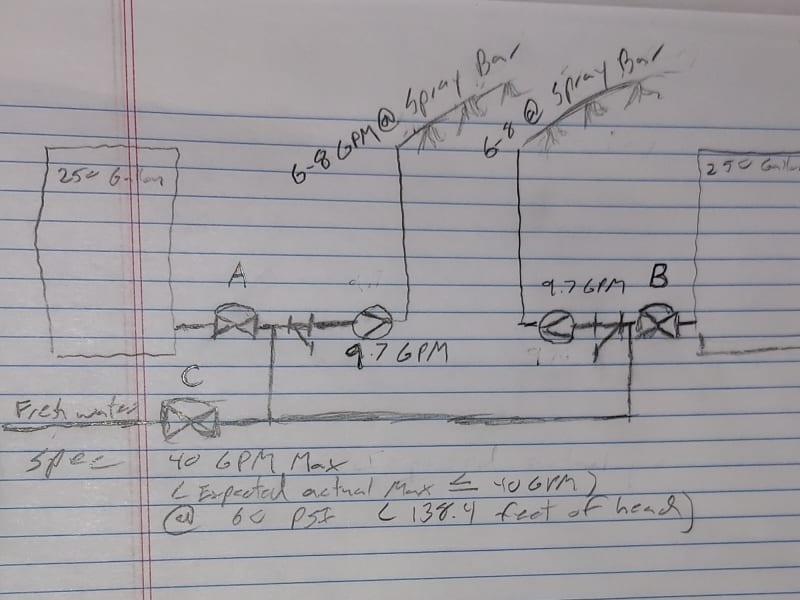
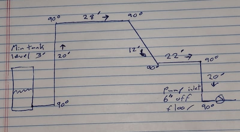
I have an application where the supply tank needs to be mounted on the other side of the room from a machine with pumps in it. I'm having trouble finding information on calculating the TDSH for this pipe configuration.

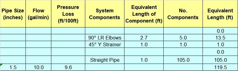
Material either 1" or 1.5" CPVC

20230816_151019_jsbedp.jpg


I believe these are the correct parameters for the calculation

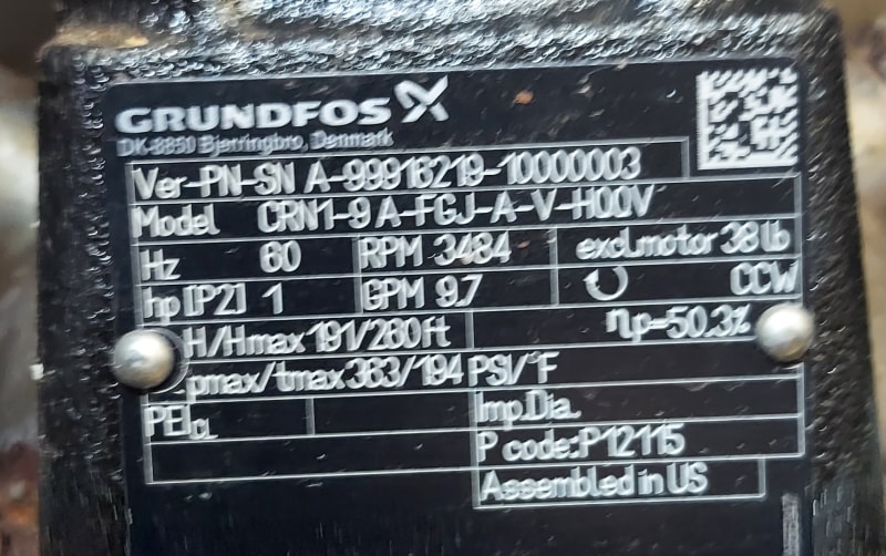
Pump Type: Vertical, multistage centrifugal pump with suction and discharge ports on the same level

+ 33.9 Standard Atmospheric Pressure (Water)
- 6.0 Altitude correction @ 5000'
- 0.82 Vapor Pressure @ 70°
- 2.0 Safety Factor (I presume this is the same 2' that's in a pump spec of "NPSHR + 2' "
- ??.? Total Dynamic Suction Lift

Then sum all those to get net positive (hopefully) suction head available.

Then subtract net positive suction head required from the NPSH pump curve. Resulting in net positive suction head.

My suspicion is I'll need to pull the pumps out of the machine and locate them at the tanks, but here's hoping.

If you could show me the math to determine TDSH I'll be able to play around with the numbers myself to see if I can get there by elevating the supply tank up.

Thanks for any help.
 
Replies continue below

Recommended for you

You don't mention friction loss which is dependant on flow rate.

Your biggest issue is the vertical lift and how you prime the system. Centrifugal pumps don't self prime and that 17ft vertical lift is close to the maximum practical lift.

Add in friction loss and if the water level and pumps are level then you have the NPSHA of the system by your calculation.

Remember - More details = better answers
Also: If you get a response it's polite to respond to it.
 
Probably want a check valve at the tank.

As you know, that's the worst possible arrangement.
Better to start your design with the best possible arrangement and make someone else tell you (in writing) to change it. So, better to just move the pumps to the tanks now and see if anybody else wants to "correct" it.

--Einstein gave the same test to students every year. When asked why he would do something like that, "Because the answers had changed."
 
You say TD(S)H, but what you seem to finding is NPSHA?

You are throwing terms about indiscriminately IMHO.

Is that 12 foot run horizontal?

Are the tank and pump at the same elevation?

But priming this loop is still your biggest issue to create the syphon you have drawn.
Not sure if this is what you're looking for?


Remember - More details = better answers
Also: If you get a response it's polite to respond to it.
 
LittleInch said:
You say TD(S)H, but what you seem to finding is NPSHA?
Yes in the end I am calculating NPSHA. However the piece of the equation I was unsure of was the calculation of TDSH. Admittedly it was really 2 questions. If I'm understanding correctly the 20' drop has no effect on TDSH.

I calculated equivalent length as 119.5'.

Untitled_xozkb2.jpg


Do I then add the 17' of lift to get a TDSH of 136.5'?

You are throwing terms about indiscriminately IMHO.
Sorry, I sure thought I was using them correctly.

Is that 12 foot run horizontal?
Yes. I can route it differently eliminating a 90.

Are the tank and pump at the same elevation?
Yes

But priming this loop is still your biggest issue to create the syphon you have drawn.
Via city water pressure at the tanks with a vent by the pump.

Not sure if this is what you're looking for?
Me either.
 
No don't add the elevation, just use the linear length to calculate frictional losses.

If you're using a pressured supply then you need to have a non return / check valve at the tank exit and flow at at least 1.5 m/ sec to blow all the air bubbles out. You will have water jetting out of the vent all over the floor or now need a drain point.

Better to fill from both ends and have an auto vent at the high point.

But unless you're going to build this and then never see it again, you will regret installing a syphon in the inlet to a pump for ever more....

Remember - More details = better answers
Also: If you get a response it's polite to respond to it.
 
Yeah I'm going to have to move them. The pumps aren't going to pull that much.

Should I need to do the math again in the future are TDSH and Equivalent length always interchangeable?
 
Fantastic decision.

--Einstein gave the same test to students every year. When asked why he would do something like that, "Because the answers had changed."
 
For the inlet / suction side of a pump NPSH is what you're finding.

Friction losses are just a part of the equation and are based on flowrate, pipe size and equivalent length.

TDH is often called Tktal Differential Head and is the differential head across the pump so TDSH is a very strange term I've not come across before.

Remember - More details = better answers
Also: If you get a response it's polite to respond to it.
 
Hi,
Check support from peers knowledgeable about fluid mechanics and pump/system otherwise you are going for troubles. Review the location of the pump, it needs a check valve at the discharge of the pump, after relocation, how do you intend to prime the system and get rid of the air pocket(s)?
I've attached a document to support your work and better communication.
Good luck anyway.
Pierre
 
 https://files.engineering.com/getfile.aspx?folder=905ed980-8dc6-42b9-9919-a1df8faf0350&file=pump.zip
The pumps in the machine won't cut it.

I'm considering feeding the spray pump with another pump. The alternative is mounting something a 25 gallon tank above the machine and topping it off as it's used.

Would I be correct in thinking along these lines.

The spray pump in it's original configuration for chemical application feeds from a non-pressurized tank with at least 3' of water above the pump inlet. It's a 9.7 GPM pump with an actual output from the spray bars between 6 and 8 GPM

At the end of the shift it has a rinse feature that blocks the chemical inlet and opens city water to the pumps. The spec sheet calls for the city water supply to be to be 40 GPM Max (Expected actual peak less than or equal to 40 GPM) @ 60 PSI with 138.4 foot of head. Which is feeding 2 pumps so I believe we can divide that by two to get 1 pump.

Would I be correct in thinking that all I would need from a supply pump standpoint is something that produces close to 10 GPM at my calculated friction loss? I'm thinking the 3 feet of water has the same effect reguardless of if it's going to the supply or spray pump so I don't need to worry about it when calculating the supply pump.

 
You're losing me.
Machine?
City water?
Rinse cycle.
Close off chemicals?
Don't know the spray pressure.
2 pumps, one pump?
If you only need 6 to 8, of course 10 might work, if discharge pressure is good.
Divide by 2?

--Einstein gave the same test to students every year. When asked why he would do something like that, "Because the answers had changed."
 
Look back at your posts and remember we only know what you tell us....

I agree with Mr 44....

Remember - More details = better answers
Also: If you get a response it's polite to respond to it.
 
Ha. Made perfect sense as I was thinking and writing about it. Definitely more rambling rereading it. Let's start with a few picture.

Pump data plate

Cart_wash_chemical_spray_pump_diagram_vt5aiy.jpg


Basic drawing of plumbing

Cart_wash_hand_simplified_han_d_drawn_OEM_plumbing_jicfzg.jpg


Now for the background.

This is a used cart wash (Think mini car wash.) It's one of those someone decided to buy even though it is configured for a different layout then we have. I've been told to make it work.

It has a chemical soak, high pressure wash, and chemical sanitizer. Each with it's own pump and set of spray bars / nozzles. We don't care about the high pressure wash.

In the original installation the chemical tanks are located within 6' of the pump inlets, at the same height, and maintain at least a 3' level. In it's new home the chemical generator and chemical tanks are going to be mounted across the room. Requiring plumping between the tanks and the machine (chemical pumps) to go up and over.

The pumps in the machine aren't strong enough to push from the tanks to the machine / spray bars. Which means relocating them to the chemical skid from within the machine is a no go.

I wanted see if it was feasible to supply the spray pump from a pump at the chemical tank.

Tank > Pump > spray pump > spray bars

The spray pumps run for around 30 seconds at a time.

The fresh water only comes in at the end of the day. Valve A and B close. C Opens and the pumps run to rinse the chemicals off the interior for the night.

I only mentioned the fresh water spec as a high max pressure for the pumps inlet.

Questions?
 
Status
Not open for further replies.
Back
Top