Continue to Site

Eng-Tips is the largest engineering community on the Internet

Intelligent Work Forums for Engineering Professionals

  • Congratulations KootK on being selected by the Eng-Tips community for having the most helpful posts in the forums last week. Way to Go!

TP square pin 2

Status
Not open for further replies.

cr7

Automotive
Dec 21, 2019
65
Hi,

similar is probably answered somewhere, but can't find it.

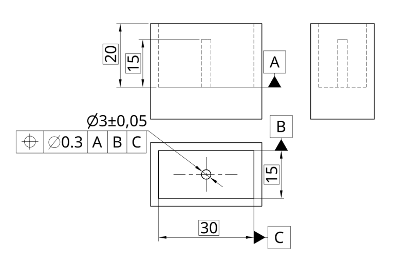
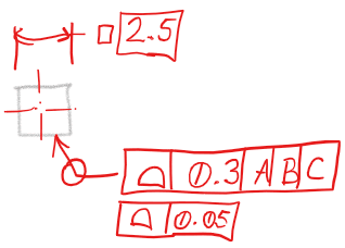
Working with ISO, is it possible to control true position (derived median line) of a square pin with only 1 characteristic like it's done with round pin?
Or, the only way is to tolerate it in each side?
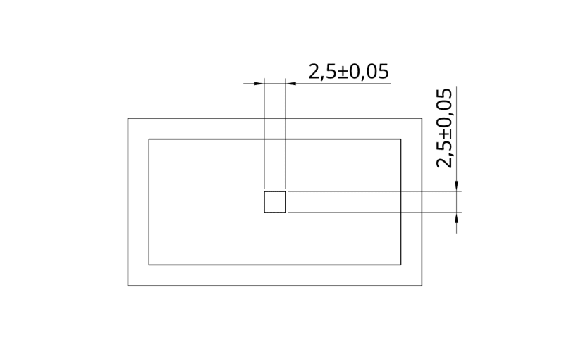
square-pin_ovzgb2.png

cyl-pin_qhtyrx.png
 
Replies continue below

Recommended for you

cr7,

First FCF controls location and orientation.
Second FCF controls size and form.

1_ivovaf.png

(In accordance with ASME Y14.5-2009)
 
Tarator,
With all due respect cf7 was asking about the ISO and not about ASME.

Now, speaking about ISO, probably one solution could be:
Profile all around 0.3 CZ to A|B|C| collection plane perpendicular with A
However, my proposed solution could / would not control derived median line as requested yet controlling the surface.

Cr7, (Cristiano Ronaldo)
By the way, why are you saying you want the derived median line and not the derived median plane for your square pin?
 
Nice try @Tarator, thank you anyway.
Now it's my turn to apologise. @Andera, others, forgive me I have a lot more to learn. I missed it with the term derived median line, I actually have in mind intersection of 2 derived median planes. I know I'm asking a lot. Jesus, is there even term in ISO GPS for that?
Andera said:
Profile all around 0.3 CZ to A|B|C| collection plane perpendicular with A
Can you elaborate, what do you mean with "collection plane perpendicular with A"?
Isn't "all around" and "CZ" conflicting here?

Feel free to "give me a lesson" on this one. You know, my primary job is playing soccer, engineering/metrology is hobbie only :D

edit: strike through silly question :)
 
cr7 said:
You know, my primary job is playing soccer....

Go and train then...(Lyon will not be an easy game) ..:):) and otherwise Bayern will kick your butt in the Champions League and poor Juve will go again empty handed during this session.

Seriously, I think Andera is correct (to the best of my knowledge) and collection plane indicator must be used if all-around profile (as proposed by Tarator) is used.
See this discussion and specially the posts from pmarc. (the best GD&T ISO expert this planet Earth has).

 
greenimi said:
Go and train then...
On the second thought, I think the soccer wil have to wait a bit, or go on without me for a while :)
Because I will (already started) try to digest the discussion you provided and all the belonging links. Looking in the 1101:2017 just a little, I *think* where @Andera is pointing. Thank you, very nice!
greenimi said:
...from pmarc. (the best GD&T ISO expert this planet Earth has).
The more I read I can agree. He is the name of the game.
 
Added strike through question 2 posts ago, as I see in 1101 that all around and CZ are friends in such case.
 
cr7,
As an extension of principles, you could draw a circle circumscribed about the square pin and apply single position tolerance directly to it. The position tolerance value would then be followed by (N) modifier, for example, that would indicate that the toleranced feature would be the associated minimum circumscribed cylinder and the axis of that cylinder would have to fall within the tolerance zone.

The approach would have some downsides, though, one of which would be the lack of orientation control (free rotation) of the square relative to datums B and C. To adress that, an orientation tolerance for at least one side of the square with respect to B or C would have to be defined anyway. Unless you would be OK with the free rotation of the pin.
 
Pmarc said:
As an extension of principles, you could draw a circle circumscribed about the square pin and apply single position tolerance directly to it. The position tolerance value would then be followed by (N) modifier, for example, that would indicate that the toleranced feature would be the associated minimum circumscribed cylinder and the axis of that cylinder would have to fall within the tolerance zone.

I am learning alot from your postings here and I would like to ask (just for my own education) for this square pin, is it legal (or valid) to use the (X) modifier to indicate the associated maximum inscribed cylinder? Or such of approach for an outside feature is forbiden by any ISO standards (because is reserved for an inside feature).

I appreciate your support.
 
Andera,
Per ISO 1101:2017: "NOTE Although the X specification element is usually used for internal features, e.g. holes as in Figure 33, it can also be used for external features, e.g. shafts".

I want to repeat one thing. I consider the proposed solution as an extension of principles as I am not aware of any example in any ISO GPS standard explicitly showing application of this tolerancing technique.
 
Thank you all. I don't mind further discussion here if anyone feels like so. Or abusing it, if there's need for :)

pmarc said:
As an extension of principles, you could draw a circle circumscribed about the square pin and apply single position tolerance directly to it. The position tolerance value would then be followed by (N) modifier, for example, that would indicate that the toleranced feature would be the associated minimum circumscribed cylinder and the axis of that cylinder would have to fall within the tolerance zone.

I especially like to push that way, because it wouldn't require any additional expensive plugins for CMM's software. As it would in surface profile variants.
(except the one with SZ, if I'm not mistaken)

pmarc said:
The approach would have some downsides, though, one of which would be the lack of orientation control (free rotation) of the square relative to datums B and C. To adress that, an orientation tolerance for at least one side of the square with respect to B or C would have to be defined anyway.

Roger that.

pmarc said:
Unless you would be OK with the free rotation of the pin.
No, I wouldn't like to leave it freely rotate.
 
Actually, since what @Andera raised about X on the pin, is valid, I like that even more.
 
Potentially - going outside with N modifier could be used on a rectangular cubiod. How nice is that!
Link (scroll down to see the post with graphics)
 
pmarc said:
As an extension of principles, you could draw a circle circumscribed about the square pin and apply single position tolerance directly to it. The position tolerance value would then be followed by (N) modifier, for example, that would indicate that the toleranced feature would be the associated minimum circumscribed cylinder and the axis of that cylinder would have to fall within the tolerance zone.

The approach would have some downsides, though, one of which would be the lack of orientation control (free rotation) of the square relative to datums B and C. To adress that, an orientation tolerance for at least one side of the square with respect to B or C would have to be defined anyway. Unless you would be OK with the free rotation of the pin.

I know I am missing something, but (just for my own uneducated ISO brain) if all the degrees of freedom are locked (as look like might be the case here since the DRF is A|B|C|) then why the orientation control is still needed? Otherwise stated why the square pin still can rotate freely? (and again I am not saying it doesn't)

And one more related question:
What means in the ISO verbiage and wording a non-redundant degrees of freedom?

Per ISO5458:2018 5.3 rule A:"When a position specification is applied to several geometrical features and the tolerance zones have at least one unlocked non-redundant degree of freedom, either the SZ or CZ or CZR modifier shall always be indicated in the tolerance section,...…..."

I cannot get/ understand what those "non-redundant" suppose to mean.

Thanks again pmarc


greenimi,

Notice that the suggested position tolerance wrt A|B|C would be applied to the circle representing minimum circumscribed cylinder, therefore it would have no control over rotation of the pin relative to datums B and C.

Regarding non-redundant degrees of freedom, I think the easiest way to explain it will be to use an example.

capture_1_e725lb.jpg


On this drawing, the non-redundant unlocked degree of freedom is the rotation of the symmetry tolerance zones about datum axis A, therefore according to the Rule A, the symmetry tolerance frame has to be supplemented with either SZ or CZ modifier (I am not sure if CZR would make any sense in this particular case and if SZ was used there would have to be another geometric tolerance controlling mutual clocking of the slots). The example of redundant unlocked degree of freedom is the translation of the symmetry tolerance zones in y direction.
 
Andera 10 Jun 20 00:20 said:
collection plane perpendicular with A
You meant collection plane parallel to A, right?
 
Status
Not open for further replies.

Part and Inventory Search

Sponsor